Ace Engineering Works Mamod SL2 'Sir Huffalot'

A very popular starting point for Live Steam. With their low cost comes a number of problems which can be discussed here
User avatar
ace
Fireman
Fireman
Posts: 294
Joined: Sun Jul 14, 2013 9:03 am

Ace Engineering Works Mamod SL2 'Sir Huffalot'

Post by ace » Sat Sep 07, 2013 3:45 pm

Well, as some members that know me from another forum maybe aware, I do have quite an extensive collection of Mamod locomotives and steam models in general.

See here:
http://modelsteam.myfreeforum.org/about65684.html

But I decided to get another one...... :roll:

Yes this is the third SL2 I have now...

So in recent light of realising that I have never actually made a Mamod my own I decided to bite the bullet and find a suitable donor. I say this because I don't actually have anything that has had its appearance changed that much.

Enter my new Mamod SL2 'Sir Huffalot'

Image

He is not in bad shape really and is nice and clean, thank you ebay seller! So the first thing I decided to do was to get it running and a bit of maintenance in the process. I have created a video of the whole account and will post up shortly. I decided to go ahead with this model as I like the light blue bodywork and spark arrester chimney, although I do not currently have any immediate plans for either the bodywork of the smoke box at the moment, so the parts will be stored for the time being (just in case I want to change this model back).

Some more angles

Image

Image

Image

I will post up some more in the near future as the developments move on. :)

Please give Sir Huffalot a warm welcome. ;)

And finally, Sir Huffalot meets Chevalier. A calm and warm hello here. :-)

Image

Chevalier is one of my favourite Mamods, see the rebuild thread here:
http://modelsteam.myfreeforum.org/about63792.html

Big Jim
Moderator
Moderator
Posts: 2694
Joined: Sat Jul 06, 2013 5:28 pm
Location: Near Llanelli

Post by Big Jim » Sat Sep 07, 2013 4:11 pm

Congratulations on winning the blue mammod. I did place a bid on it myself, sorry if I raised the price for you! I may have a blue cab back if you want it (and if I can find it, I will have a look tonight)

User avatar
ace
Fireman
Fireman
Posts: 294
Joined: Sun Jul 14, 2013 9:03 am

Post by ace » Sat Sep 07, 2013 4:46 pm

Big Jim:88044 wrote:Congratulations on winning the blue mammod. I did place a bid on it myself, sorry if I raised the price for you! I may have a blue cab back if you want it (and if I can find it, I will have a look tonight)
Hi Jim, yes I feel quite lucky. I was only a couple of quid off the highest bid. So it could have been anyone's. :)

If you have a blue back somewhere that would be really useful, PM me if you find it. ;)

User avatar
Chris Cairns
Driver
Driver
Posts: 2366
Joined: Mon Oct 29, 2007 7:25 pm
Location: Glasgow, Scotland

Post by Chris Cairns » Sat Sep 07, 2013 6:14 pm

You are certainly building an extensive Mamod/MSS collection Ace.

I originally had a plan of getting one of each of the different Mamod SL's to run and record some video. However at that time the SL2 & SL6 were either in short supply or too expensive.

The SL2 was apparently aimed at the American market but was not successful and was only produced for under 2 years (both in the RS2 set and individually). The brass spark arrester balloon on the SL3 was much more successful.

Looks like 2 items on your SL2 are not original - when they were produced the cylinder backplate would have been riveted to the chassis frames, the alternative screws & nuts fixing was introduced in 1983 with the SL1K, and similarly the whistle operating lever would have been fitted to the bracket with an eyelet, again the alternative screw & nut fixing was introduced with the SL1K.

Hope you are successful in your quest for a matching blue cab back.

Look forward to viewing your video in due course.

Chris Cairns.

User avatar
ace
Fireman
Fireman
Posts: 294
Joined: Sun Jul 14, 2013 9:03 am

Post by ace » Sat Sep 07, 2013 7:58 pm

Hi Chris, thanks for the history lesson. Everyday is a day at school. ;)

I was aware of the rivets and pressed whistle pin/tube. My unfired SL2 has both of those things and my other well used SL2 had them too before I did some essential maintenance. I am not surprised however being it could be as much as 30 years old now. That is as old as me!

The ugly side of this one is seen below, a repair on the reverser using solder other than o rings. A more permanent repair no doubt, but more difficult either way. Nothing a quick scorch with a blow torch can't sort.

This was quite evident from the listing pictures so I knew what I was buying into. :)

Image

User avatar
Chris Cairns
Driver
Driver
Posts: 2366
Joined: Mon Oct 29, 2007 7:25 pm
Location: Glasgow, Scotland

Post by Chris Cairns » Sat Sep 07, 2013 8:26 pm

I've never had any big problems with those 'O' rings leaking but can understand why some owners solder the pipes in instead. I would also recommend using some 0.5mm oil resistant gasket paper between the chassis frames and the reverser/regulator valve - I find that more effective than using gasket sealant.

Looks like the chassis has had a bit of work done on it - 2nd spring on the reverser/regulator pivot bolt and the screws & nuts that replaced the rivets have been overtightened thus badly bending the already flexible chassis frames.

Chris Cairns.

PS - SL2 produced in 1980/1981 so at least 32 years old.

User avatar
ace
Fireman
Fireman
Posts: 294
Joined: Sun Jul 14, 2013 9:03 am

Post by ace » Sat Sep 07, 2013 10:09 pm

I have had problems with the o rings but only in one or two modified ones where the steam pipe was home made and was obviously problematic to locate at exactly the correct angle, so were soldered.

Other than that I could not recommend the standard set up enough. It is a shame about those frames, but at least they can be straightened and amazingly enough didn't hinder performance at all.

Well steaming proved to be a very rewarding time indeed, despite the problems. The little locomotive ran so well that I nearly decided to keep it as it.

Image

Image

Here is the promised video of the SL2

<object width="800" height="600"><param name="movie" value="//www.youtube.com/v/igiv76ZIUCI?hl=en_GB& ... ram><param name="allowFullScreen" value="true"></param><param name="allowscriptaccess" value="always"></param><embed src="//www.youtube.com/v/igiv76ZIUCI?hl=en_GB&version=3&rel=0" type="application/x-shockwave-flash" width="800" height="600" allowscriptaccess="always" allowfullscreen="true"></embed></object>

User avatar
Chris Cairns
Driver
Driver
Posts: 2366
Joined: Mon Oct 29, 2007 7:25 pm
Location: Glasgow, Scotland

Post by Chris Cairns » Sun Sep 08, 2013 1:19 am

Great video Ace, and it shows a couple more modifications to your SL2.

The safety valve was upgraded by tightening the spring (the crimped portion on the rod is further up) although they used a cheap spring which has rusted through.

And the main steam pipe has been soldered into the top of the tube in the boiler. Others will tell you that this was done at the factory, but I have not experienced this with any of my Mamod SL's and thus believe it was done by owners after purchase. It was however done by MSS on my Saddle Tank.

Your priming is probably an indication that you need to flush out the boiler.

Which oil are you using as I noticed you used the same oil for everything? I use steam oil (460 or 220) for the cylinders & reverser/regulator and 3 in 1 type oil for the rest.

Chris Cairns.

User avatar
ace
Fireman
Fireman
Posts: 294
Joined: Sun Jul 14, 2013 9:03 am

Post by ace » Sun Sep 08, 2013 8:50 am

Hi Chris,

The soldered steam pipe I have experienced on 6 of my models. On the one SL3, 3x SL2s and on both my SL4s. My unfired SL4, SL3 and SL2 are all this way too so undoubtably they did this at the factory.

That being said explains that they did this for many productions years and cannot be pinned to a specific build year.

As for the safety valve, if the additional pressing was done after production they have a very exact way to replicate the factory pressing. I see what you are saying with regard to it being 'modified' but I think it may have bought as an upgrade part instead.

The square pressing looks too neat to be a 'home brew' modification. I know it isn't totally clear from this image, but you can just make it out.

The oil I am using is 460 steam oil for the steam pipe and I have an identical looking oil can with 10-40w semi synthetic engine oil for the bushes and crank joints.

Image

User avatar
Chris Cairns
Driver
Driver
Posts: 2366
Joined: Mon Oct 29, 2007 7:25 pm
Location: Glasgow, Scotland

Post by Chris Cairns » Sun Sep 08, 2013 9:24 am

Hi Ace, I guess I have just been lucky with not having any Mamod steam pipes soldered up. As a Mamod historian it would be good to put a date to this practise. Your SL2 & SL4 would probably date it to 1981, and if your SL3 has a smooth sided smoke box casting (the additional bulge for the side tank tabs came later) and the key ring type coupling ring that would confirm it as 1981. That was during the Mamod 80 Limited period, who also seem to be responsible for drilling the holes in display model boilers to prevent them being sold.

Your safety valve does not look like a Mamod one (they normally used stainless steel springs which would not rust so much) so it is either made using a safety valve repair kit sold by an after market supplier (cannot remember who sold these) or one of the replica safety valves made by the likes of Manor Models.

Chris Cairns

User avatar
ace
Fireman
Fireman
Posts: 294
Joined: Sun Jul 14, 2013 9:03 am

Post by ace » Sun Sep 08, 2013 9:35 am

Ahh, I see. So the soldered steam pipes were during the early days. They had probably ran out of spings! :lol:

And a reproduction SV. It doesn't look too bad to be honest.

Because of your comments on the Saddle tank, I had a peek under my Mss jubilee dome and that one has a spring. I guess they soldered the saddle tank pipe in because it is shorter to allow for the squat dome. I suppose MSS couldn't use the spring there because there would be no pipe to support it, thus enabling it to bend out of its 'correct' position and ping off inside the dome.

User avatar
Chris Cairns
Driver
Driver
Posts: 2366
Joined: Mon Oct 29, 2007 7:25 pm
Location: Glasgow, Scotland

Post by Chris Cairns » Sun Sep 08, 2013 9:45 am

I had not thought that it was due to a lack of suitable springs, but entirely possible.

The current Mamod made a higher pressure safety valve for the Golden Jubilee & William locomotives (approx 25 PSI) but the shaft is not finished like yours, and their current locomotives have a 40 PSI version so I have to be careful to not get them mixed up.

Chris Cairns.

Big Jim
Moderator
Moderator
Posts: 2694
Joined: Sat Jul 06, 2013 5:28 pm
Location: Near Llanelli

Post by Big Jim » Sun Sep 08, 2013 4:49 pm

Regarding soldered steam pipes.
I aquired a new loco around 1990 that was a bit of a friday afternoon job. No it was a lot of a friday afternoon job with multiple issues.
It was returned to the factory and when I got it back it had soldered joints on the reversing block. Which was a bit of a pain as I wanted to fit a lubricator and regulator.
If at first you don't succeed, use a bigger hammer!

User avatar
ace
Fireman
Fireman
Posts: 294
Joined: Sun Jul 14, 2013 9:03 am

Post by ace » Mon Sep 09, 2013 12:21 am

Right, I have been busy today and busy this evening. I have done some critical updates and have some results to report in. Some images.

It was a shame to do it but I have started! ;)

Image

Image

Soaked in a ultrasonic bath

Image

Like new

Image

Some modification required on the port holes on the chassis

Image

Image

Image

Stripped and soldered the boiler

Image

Image

Image

Assembled boiler

Image

Assembled chassis

Image

And a video

<object width="800" height="600"><param name="movie" value="//www.youtube.com/v/eGvriboAzzs?hl=en_GB& ... ram><param name="allowFullScreen" value="true"></param><param name="allowscriptaccess" value="always"></param><embed src="//www.youtube.com/v/eGvriboAzzs?hl=en_GB&version=3&rel=0" type="application/x-shockwave-flash" width="800" height="600" allowscriptaccess="always" allowfullscreen="true"></embed></object>

Narrow Minded
Driver
Driver
Posts: 4650
Joined: Wed Dec 30, 2009 2:27 pm
Location: Forgotten Realms
Contact:

Post by Narrow Minded » Mon Sep 09, 2013 1:05 pm

Excellent stuff and well described progress :D
Image

User avatar
Chris Cairns
Driver
Driver
Posts: 2366
Joined: Mon Oct 29, 2007 7:25 pm
Location: Glasgow, Scotland

Post by Chris Cairns » Tue Sep 10, 2013 5:32 pm

Brilliant video Ace - I particularly liked the timeline of the dismantling.

Some questions/points: -

1. You say you have silver soldered the boiler inserts and a question about that has been asked on the other Forum. I was initially led to believe that soft soldered joints could not then be silver soldered, but I've since been advised that as long as you remove the soft solder and clean off any remains of the flux the joint can then be silver soldered. So what solder do you use and how do you do them (as the front recessed boiler end is also soft soldered and I've had one leak on an MSS boiler possibly from the heat of soldering some 6BA nuts on the inside for a better method of retaining the boiler than those silly posidrive screws).

2. IP Engineering cylinders, or their 'O' ring piston upgrade kits had gland nuts. Your cylinders are the same as fitted to my Samson Locomotive Works 'super Mamod' Ginny.

Image

For more photos of 'Ginny' see here - http://gardenrails.myfreeforum.org/about475.html

3. I see you have solved the problem with the misaligned RWM reverser/regulator valve. When I refurbish a Mamod/MSS I drill out those holes to 1/8"/3mm as recommended in the 16mmngm Mamod e-book, and I also check the gaskets as well which usually need some filing to open out the slots and line up with the various holes. Some owners fit those reverser/regulator valves to the chassis using gasket compound, but I prefer to use oil resistant gasket paper.

Nice to see RWM are doing the cab mounted regulator again, although he needs to update his website to reflect that fact to potential buyers as they are still greeted with the "Awaiting new stock" message at present. The other ones I've seen fitted have a gasket behind the nut that secures the regulator body into the boiler 'T' piece.

As you are not using the SL2 bodywork I'm intrigued as to what you will be creating here. Looking forward to future updates.

Chris Cairns.

User avatar
ace
Fireman
Fireman
Posts: 294
Joined: Sun Jul 14, 2013 9:03 am

Post by ace » Tue Sep 10, 2013 6:49 pm

Thanks for the compliments guys. Chris I shall answer your questions as best I can below.
Chris Cairns:88284 wrote: 1. You say you have silver soldered the boiler inserts and a question about that has been asked on the other Forum. I was initially led to believe that soft soldered joints could not then be silver soldered, but I've since been advised that as long as you remove the soft solder and clean off any remains of the flux the joint can then be silver soldered. So what solder do you use and how do you do them (as the front recessed boiler end is also soft soldered and I've had one leak on an MSS boiler possibly from the heat of soldering some 6BA nuts on the inside for a better method of retaining the boiler than those silly posidrive screws).
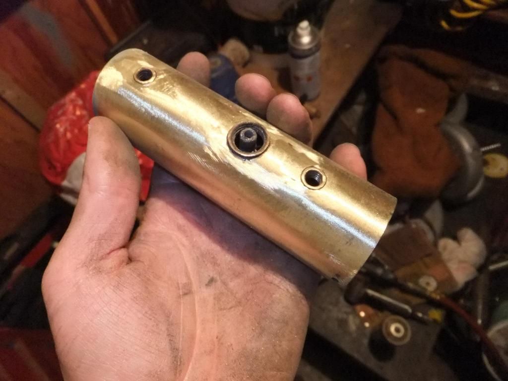
Right, as for the soft soldering of the joints I fail to have seen much if any at all on this model. From what I can gather this boiler may have been boiled dry a few times in its life and consequently the solder was rattling around inside. In order to clean it all off I use my Dremel with a small s/steel attachment and whizz around the inserts to make sure they are as clean as possible. The silver solder then just flows beautifully once all fluxed up. I tend to wrap the boiler in fibreglass heatproof matting as much as possible to retain the heat in the work. It is very easy to overheat the brass and ruin the boiler, I learned this the hard way once. As for the solder I use 842 brazing rods or easy flow which tends to work well with these. I believe these are 42% brazing alloy and a mix of cadmium.

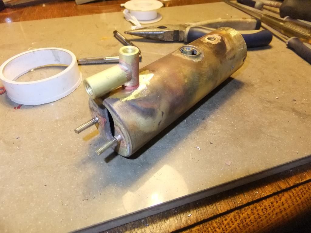
For the end cap sometimes I am lucky and I can get the cap off completely. By heating and poking a wooden dowel through the sight glass hole and gently going around the whole perimeter of the soft solder. Then it is just the clean up and re solder back with silver solder. If not I just heat the work enough to bash the boiler on the sight glass end to remove as much excess as possible and then flow some silver solder in. To be honest I never have a problem with this type of solder mixing incorrectly. It seems to work perfectly. I have only done this once on one boiler but it works on a standard safety valve only.
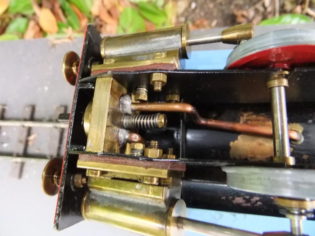
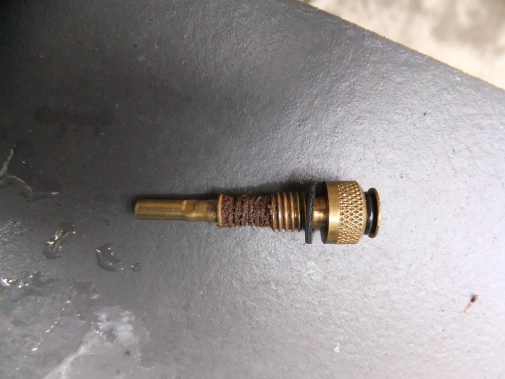
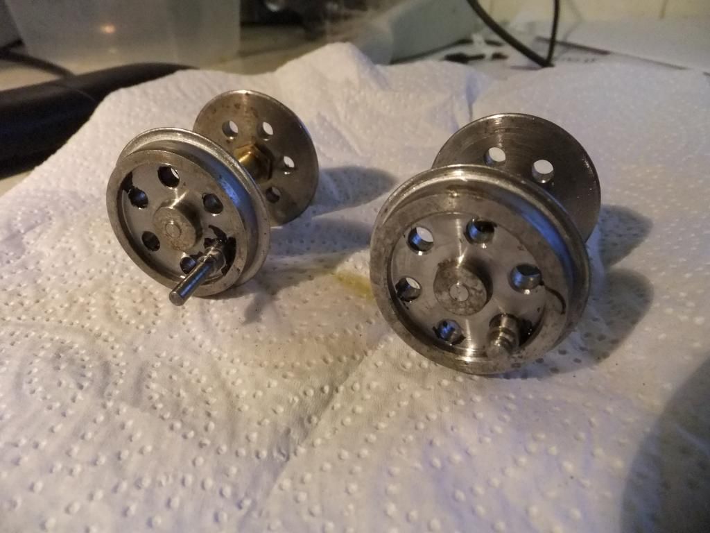
Chris Cairns:88284 wrote:2.IP Engineering cylinders, or their 'O' ring piston upgrade kits had gland nuts. Your cylinders are the same as fitted to my Samson Locomotive Works 'super Mamod' Ginny.

For more photos of 'Ginny' see here - http://gardenrails.myfreeforum.org/about475.html
Thanks for the info on the cylinders they aren't cylinder upgrade kits they are the full deal. To be honest they look very similar to my dream steam cylinders on my other model. Maybe slightly different gland nuts. Thanks for the link and image by the way. :)

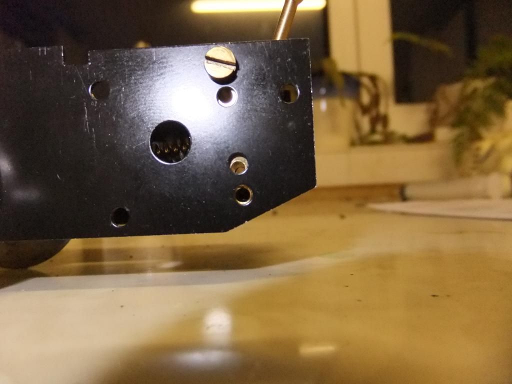
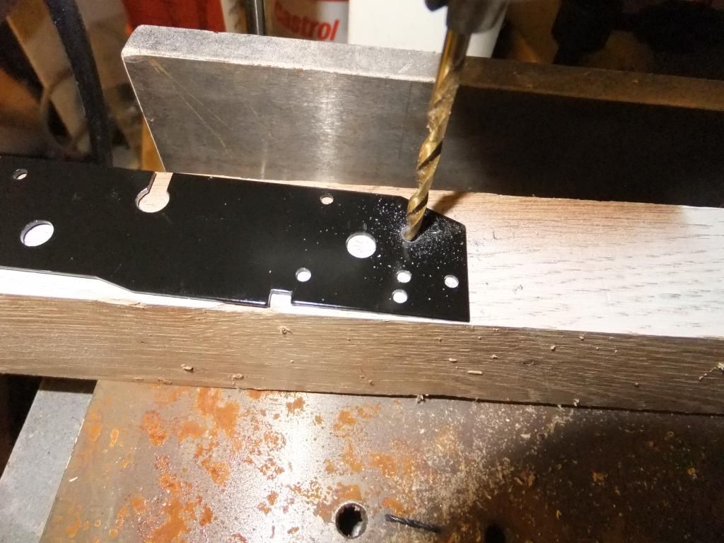
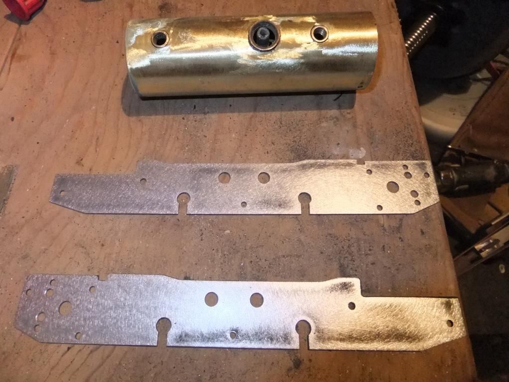
Chris Cairns:88284 wrote:3. I see you have solved the problem with the misaligned RWM reverser/regulator valve. When I refurbish a Mamod/MSS I drill out those holes to 1/8"/3mm as recommended in the 16mmngm Mamod e-book, and I also check the gaskets as well which usually need some filing to open out the slots and line up with the various holes. Some owners fit those reverser/regulator valves to the chassis using gasket compound, but I prefer to use oil resistant gasket paper.

Nice to see RWM are doing the cab mounted regulator again, although he needs to update his website to reflect that fact to potential buyers as they are still greeted with the "Awaiting new stock" message at present. The other ones I've seen fitted have a gasket behind the nut that secures the regulator body into the boiler 'T' piece.
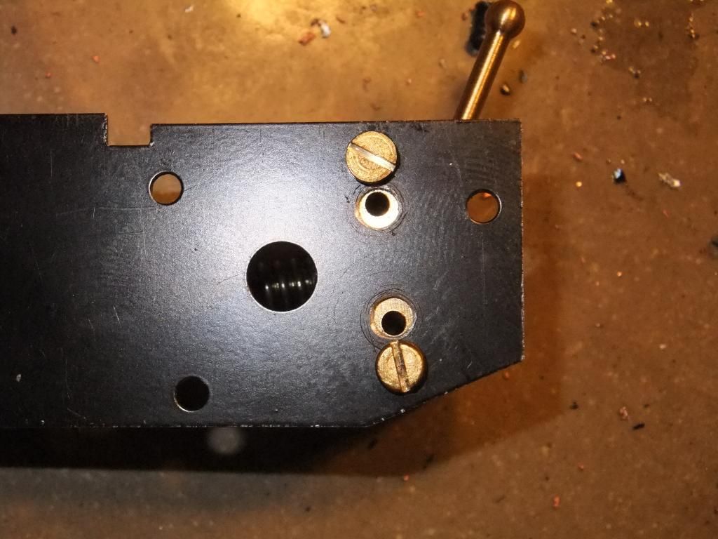
Well I haven't sorted my RWM reverser valve yet, it was left kicking around so I used it. The original one as you have seen was soldered to the steam pipes so I haven't undone all that yet to pop this valve in.

I was unaware of the 3mm hole recommendation, I just drilled them out because they were mis aligned and yes the gasket was also to match. I normally do this on my upgraded models for a little extra out of them.

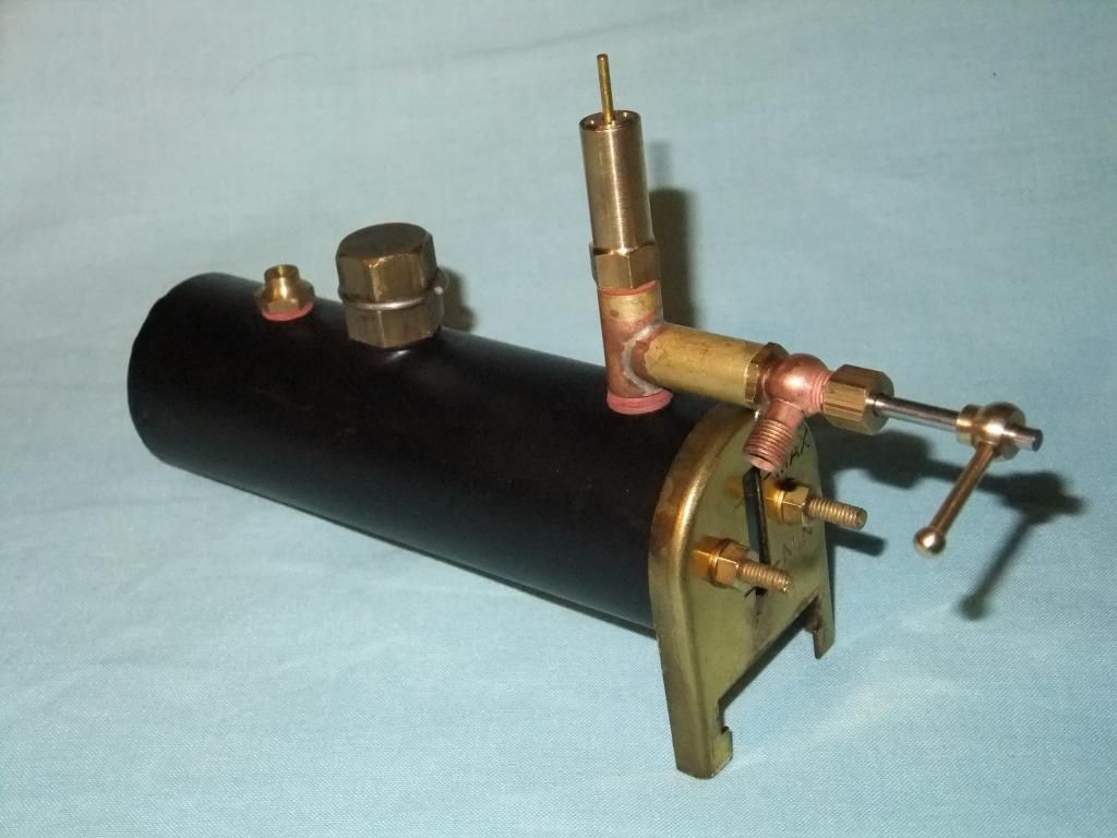
The RWM cab mounted regulator is still not in stock. This one was one that Roy made for me to trial and come back to him. The only problem with it is ( if you can call it a problem) that the safety valve thread size is 40tpi. I did want to have the flexibility of fitting a whistle in there and have put it to Roy. As for a gasket I used PTFE tape between the reg body and the T piece.

As for fitting the reverser between the frames I prefer to use a smidge of gasket sealer. Just a wipe with a finger, hardly any at all. I mean, they seal ok without any gasket compound I find. Especially after painting when the paint is still a little soft so it moulds to the shape of the mating surfaces of the parts.

Tbh it really is down to personal preference. I cannot see anything wrong using either method if done correctly.
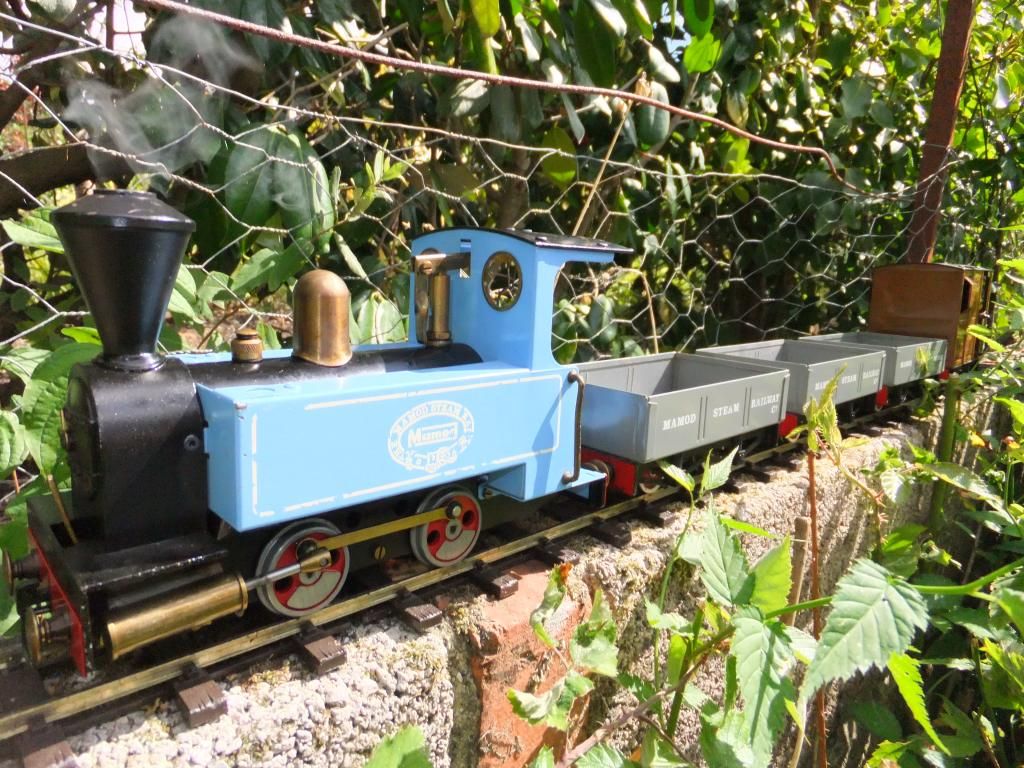
Chris Cairns:88284 wrote:As you are not using the SL2 bodywork I'm intrigued as to what you will be creating here. Looking forward to future updates.
Well as for the bodywork, you will have to wait and see. I have a rod in the fire at the moment and am getting ready to start making. I need to do this soon so I can route all the pipe work how I want to. And get the model going properly.

User avatar
Chris Cairns
Driver
Driver
Posts: 2366
Joined: Mon Oct 29, 2007 7:25 pm
Location: Glasgow, Scotland

Post by Chris Cairns » Tue Sep 10, 2013 7:45 pm

Hi Ace,

Many thanks for the prompt reply. If you have not already seen it this video shows how a Mamod boiler is constructed (although it is not a loco boiler) - start from 00:34 - http://youtu.be/V9c83qO08HM Over on the Unofficial Mamod Forums they have found that some of these later boiler inserts have just been punched into the boiler with no solder or solder paste, but that was after the original Mamod Steam Railway went out of production.

I agree with your thinking on the RWM cab mounted regulator. These were originally made by IP Eng & PPS and were to be used on a standard Mamod/MSS boiler thus the fittings should all be 1/4" x 28BSF. That is what the current Dream Steam version is.

Chris Cairns.

User avatar
ace
Fireman
Fireman
Posts: 294
Joined: Sun Jul 14, 2013 9:03 am

Post by ace » Tue Sep 10, 2013 8:14 pm

Thanks for the link Chris. That really helps me understand how the models become what they are. Nice to see a William at the end too.

I understand that they didn't use solder or solder paste, but did they really think it would last? I mean, I have seen so many spinning inserts I don't care to think about so I just solder the boilers up as part of my process if I intend to keep it.

My MSS golden jubilee that I don't often run needs this doing now too. I must have ran it only half a dozen times and probably over the course of several years of ownership. I just don't see the logic in it, why not just solder the boilers... :roll:

User avatar
Chris Cairns
Driver
Driver
Posts: 2366
Joined: Mon Oct 29, 2007 7:25 pm
Location: Glasgow, Scotland

Post by Chris Cairns » Tue Sep 10, 2013 8:33 pm

As far as I'm aware Mamod used solder paste on all of the SL boilers, and similarly MSS uses solder paste on their loco boilers as well (although probably not enough as owners have found out to their cost).

I guess it is all a matter of keeping costs down by having the boilers made in batches rather than the individuality that soldering all the boiler inserts would cause in extra man hours. That is probably why the current Mamod locomotives are more expensive as the boilers are silver soldered, and the wheel sets & oscillating cylinders are made for (not by) Mamod.

I have a selection of soldering tips for my butane torch but putting one of these into an insert did not seem to get it hot enough to remelt the solder paste so you have to end up damaging the surrounding paintwork by using the open flame option.

Chris Cairns.

Post Reply

Who is online

Users browsing this forum: No registered users and 8 guests