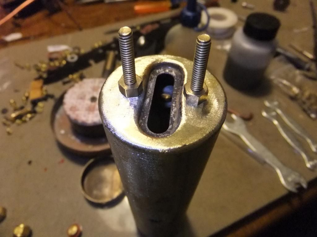
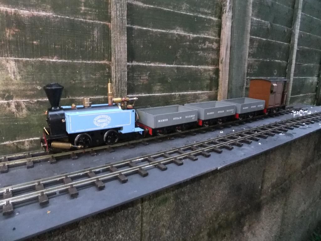
Ace Engineering Works Mamod SL2 'Sir Huffalot'

A very popular starting point for Live Steam. With their low cost comes a number of problems which can be discussed here
User avatar
Chris Cairns
Driver
Driver
Posts: 2366
Joined: Mon Oct 29, 2007 7:25 pm
Location: Glasgow, Scotland

Post by Chris Cairns » Tue Sep 10, 2013 5:32 pm

Brilliant video Ace - I particularly liked the timeline of the dismantling.

Some questions/points: -

1. You say you have silver soldered the boiler inserts and a question about that has been asked on the other Forum. I was initially led to believe that soft soldered joints could not then be silver soldered, but I've since been advised that as long as you remove the soft solder and clean off any remains of the flux the joint can then be silver soldered. So what solder do you use and how do you do them (as the front recessed boiler end is also soft soldered and I've had one leak on an MSS boiler possibly from the heat of soldering some 6BA nuts on the inside for a better method of retaining the boiler than those silly posidrive screws).

2. IP Engineering cylinders, or their 'O' ring piston upgrade kits had gland nuts. Your cylinders are the same as fitted to my Samson Locomotive Works 'super Mamod' Ginny.

Image

For more photos of 'Ginny' see here - http://gardenrails.myfreeforum.org/about475.html

3. I see you have solved the problem with the misaligned RWM reverser/regulator valve. When I refurbish a Mamod/MSS I drill out those holes to 1/8"/3mm as recommended in the 16mmngm Mamod e-book, and I also check the gaskets as well which usually need some filing to open out the slots and line up with the various holes. Some owners fit those reverser/regulator valves to the chassis using gasket compound, but I prefer to use oil resistant gasket paper.

Nice to see RWM are doing the cab mounted regulator again, although he needs to update his website to reflect that fact to potential buyers as they are still greeted with the "Awaiting new stock" message at present. The other ones I've seen fitted have a gasket behind the nut that secures the regulator body into the boiler 'T' piece.

As you are not using the SL2 bodywork I'm intrigued as to what you will be creating here. Looking forward to future updates.

Chris Cairns.

User avatar
ace
Fireman
Fireman
Posts: 294
Joined: Sun Jul 14, 2013 9:03 am

Post by ace » Tue Sep 10, 2013 6:49 pm

Thanks for the compliments guys. Chris I shall answer your questions as best I can below.
Chris Cairns:88284 wrote: 1. You say you have silver soldered the boiler inserts and a question about that has been asked on the other Forum. I was initially led to believe that soft soldered joints could not then be silver soldered, but I've since been advised that as long as you remove the soft solder and clean off any remains of the flux the joint can then be silver soldered. So what solder do you use and how do you do them (as the front recessed boiler end is also soft soldered and I've had one leak on an MSS boiler possibly from the heat of soldering some 6BA nuts on the inside for a better method of retaining the boiler than those silly posidrive screws).
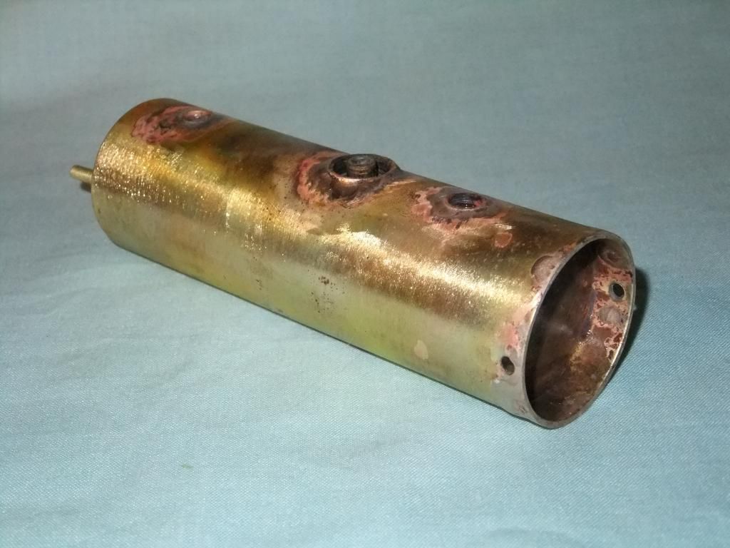
Right, as for the soft soldering of the joints I fail to have seen much if any at all on this model. From what I can gather this boiler may have been boiled dry a few times in its life and consequently the solder was rattling around inside. In order to clean it all off I use my Dremel with a small s/steel attachment and whizz around the inserts to make sure they are as clean as possible. The silver solder then just flows beautifully once all fluxed up. I tend to wrap the boiler in fibreglass heatproof matting as much as possible to retain the heat in the work. It is very easy to overheat the brass and ruin the boiler, I learned this the hard way once. As for the solder I use 842 brazing rods or easy flow which tends to work well with these. I believe these are 42% brazing alloy and a mix of cadmium.

For the end cap sometimes I am lucky and I can get the cap off completely. By heating and poking a wooden dowel through the sight glass hole and gently going around the whole perimeter of the soft solder. Then it is just the clean up and re solder back with silver solder. If not I just heat the work enough to bash the boiler on the sight glass end to remove as much excess as possible and then flow some silver solder in. To be honest I never have a problem with this type of solder mixing incorrectly. It seems to work perfectly. I have only done this once on one boiler but it works on a standard safety valve only.
Chris Cairns:88284 wrote:2.IP Engineering cylinders, or their 'O' ring piston upgrade kits had gland nuts. Your cylinders are the same as fitted to my Samson Locomotive Works 'super Mamod' Ginny.

For more photos of 'Ginny' see here - http://gardenrails.myfreeforum.org/about475.html
Thanks for the info on the cylinders they aren't cylinder upgrade kits they are the full deal. To be honest they look very similar to my dream steam cylinders on my other model. Maybe slightly different gland nuts. Thanks for the link and image by the way. :)

Chris Cairns:88284 wrote:3. I see you have solved the problem with the misaligned RWM reverser/regulator valve. When I refurbish a Mamod/MSS I drill out those holes to 1/8"/3mm as recommended in the 16mmngm Mamod e-book, and I also check the gaskets as well which usually need some filing to open out the slots and line up with the various holes. Some owners fit those reverser/regulator valves to the chassis using gasket compound, but I prefer to use oil resistant gasket paper.

Nice to see RWM are doing the cab mounted regulator again, although he needs to update his website to reflect that fact to potential buyers as they are still greeted with the "Awaiting new stock" message at present. The other ones I've seen fitted have a gasket behind the nut that secures the regulator body into the boiler 'T' piece.
Well I haven't sorted my RWM reverser valve yet, it was left kicking around so I used it. The original one as you have seen was soldered to the steam pipes so I haven't undone all that yet to pop this valve in.

I was unaware of the 3mm hole recommendation, I just drilled them out because they were mis aligned and yes the gasket was also to match. I normally do this on my upgraded models for a little extra out of them.

The RWM cab mounted regulator is still not in stock. This one was one that Roy made for me to trial and come back to him. The only problem with it is ( if you can call it a problem) that the safety valve thread size is 40tpi. I did want to have the flexibility of fitting a whistle in there and have put it to Roy. As for a gasket I used PTFE tape between the reg body and the T piece.

As for fitting the reverser between the frames I prefer to use a smidge of gasket sealer. Just a wipe with a finger, hardly any at all. I mean, they seal ok without any gasket compound I find. Especially after painting when the paint is still a little soft so it moulds to the shape of the mating surfaces of the parts.

Tbh it really is down to personal preference. I cannot see anything wrong using either method if done correctly.
Chris Cairns:88284 wrote:As you are not using the SL2 bodywork I'm intrigued as to what you will be creating here. Looking forward to future updates.
Well as for the bodywork, you will have to wait and see. I have a rod in the fire at the moment and am getting ready to start making. I need to do this soon so I can route all the pipe work how I want to. And get the model going properly.

User avatar
Chris Cairns
Driver
Driver
Posts: 2366
Joined: Mon Oct 29, 2007 7:25 pm
Location: Glasgow, Scotland

Post by Chris Cairns » Tue Sep 10, 2013 7:45 pm

Hi Ace,

Many thanks for the prompt reply. If you have not already seen it this video shows how a Mamod boiler is constructed (although it is not a loco boiler) - start from 00:34 - http://youtu.be/V9c83qO08HM Over on the Unofficial Mamod Forums they have found that some of these later boiler inserts have just been punched into the boiler with no solder or solder paste, but that was after the original Mamod Steam Railway went out of production.

I agree with your thinking on the RWM cab mounted regulator. These were originally made by IP Eng & PPS and were to be used on a standard Mamod/MSS boiler thus the fittings should all be 1/4" x 28BSF. That is what the current Dream Steam version is.

Chris Cairns.

User avatar
ace
Fireman
Fireman
Posts: 294
Joined: Sun Jul 14, 2013 9:03 am

Post by ace » Tue Sep 10, 2013 8:14 pm

Thanks for the link Chris. That really helps me understand how the models become what they are. Nice to see a William at the end too.

I understand that they didn't use solder or solder paste, but did they really think it would last? I mean, I have seen so many spinning inserts I don't care to think about so I just solder the boilers up as part of my process if I intend to keep it.

My MSS golden jubilee that I don't often run needs this doing now too. I must have ran it only half a dozen times and probably over the course of several years of ownership. I just don't see the logic in it, why not just solder the boilers... :roll:

User avatar
Chris Cairns
Driver
Driver
Posts: 2366
Joined: Mon Oct 29, 2007 7:25 pm
Location: Glasgow, Scotland

Post by Chris Cairns » Tue Sep 10, 2013 8:33 pm

As far as I'm aware Mamod used solder paste on all of the SL boilers, and similarly MSS uses solder paste on their loco boilers as well (although probably not enough as owners have found out to their cost).

I guess it is all a matter of keeping costs down by having the boilers made in batches rather than the individuality that soldering all the boiler inserts would cause in extra man hours. That is probably why the current Mamod locomotives are more expensive as the boilers are silver soldered, and the wheel sets & oscillating cylinders are made for (not by) Mamod.

I have a selection of soldering tips for my butane torch but putting one of these into an insert did not seem to get it hot enough to remelt the solder paste so you have to end up damaging the surrounding paintwork by using the open flame option.

Chris Cairns.

User avatar
ace
Fireman
Fireman
Posts: 294
Joined: Sun Jul 14, 2013 9:03 am

Post by ace » Tue Sep 10, 2013 8:42 pm

Chris Cairns:88305 wrote:As far as I'm aware Mamod used solder paste on all of the SL boilers, and similarly MSS uses solder paste on their loco boilers as well (although probably not enough as owners have found out to their cost).

I guess it is all a matter of keeping costs down by having the boilers made in batches rather than the individuality that soldering all the boiler inserts would cause in extra man hours. That is probably why the current Mamod locomotives are more expensive as the boilers are silver soldered, and the wheel sets & oscillating cylinders are made for (not by) Mamod.

I have a selection of soldering tips for my butane torch but putting one of these into an insert did not seem to get it hot enough to remelt the solder paste so you have to end up damaging the surrounding paintwork by using the open flame option.

Chris Cairns.
Absolutely Chris, the remainder of the boiler just takes too much away from the solder area. Forget the paint, a blow torch is the only way to go there.

Even something as just a little bigger like a roundhouse copper boiler is still too much for a blow torch. The last time I had to solder my Billy boiler, I took it to work wrapped it in the fibreglass matting and used the oxy acetylene torch set. That just heated the area up in seconds. Overkill? Maybe but the job was done neatly and with out fuss.

Having said all that copper is an excellent heat conductor so it is of no wonder the blowtorch struggled.

User avatar
ace
Fireman
Fireman
Posts: 294
Joined: Sun Jul 14, 2013 9:03 am

Post by ace » Tue Sep 10, 2013 9:22 pm

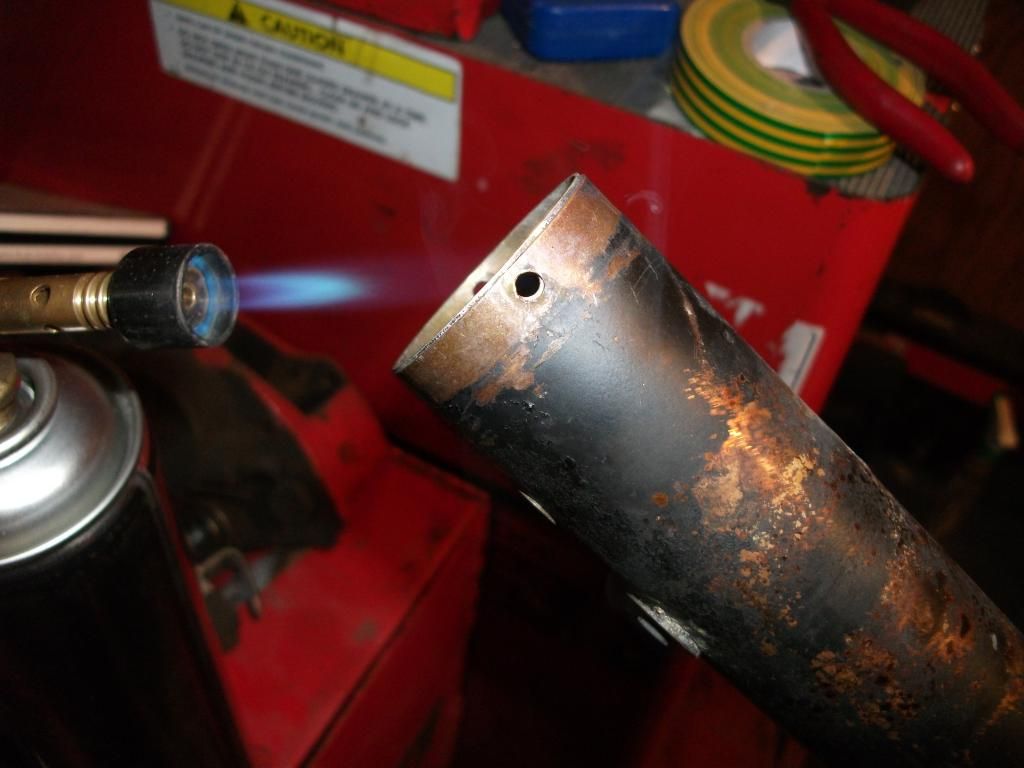
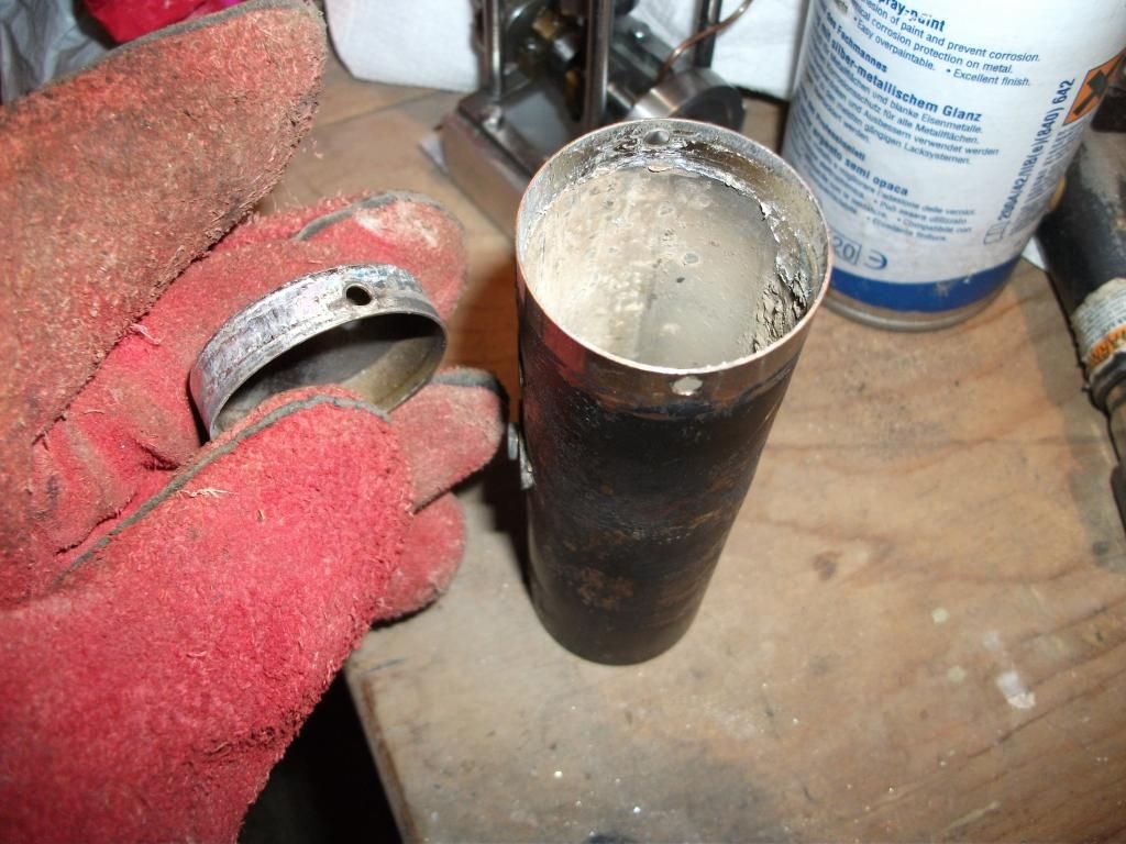
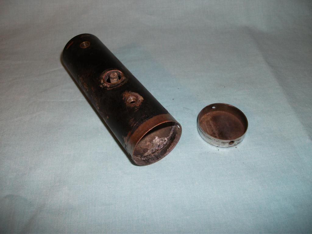
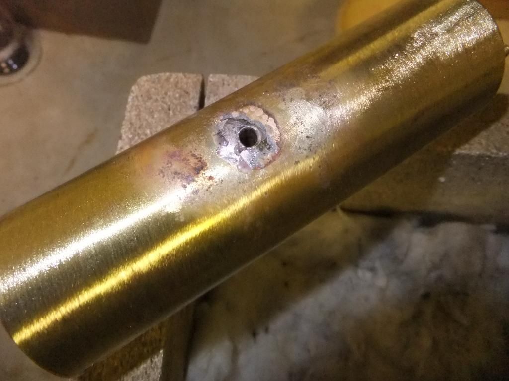
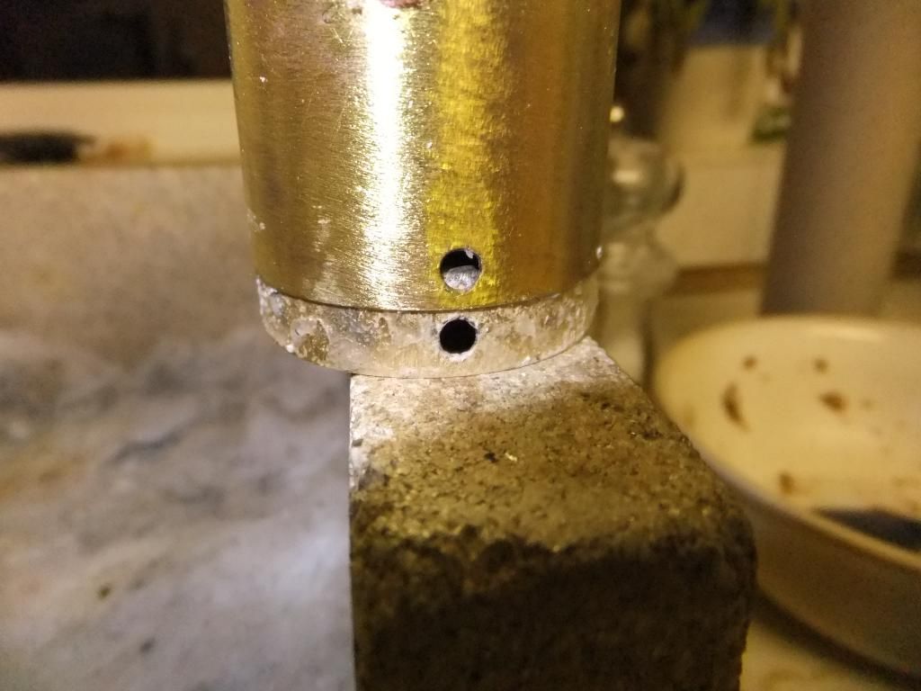
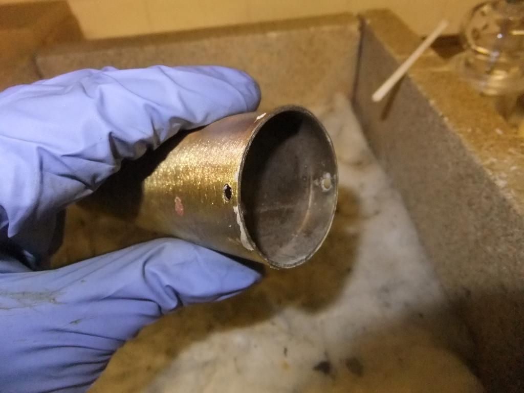
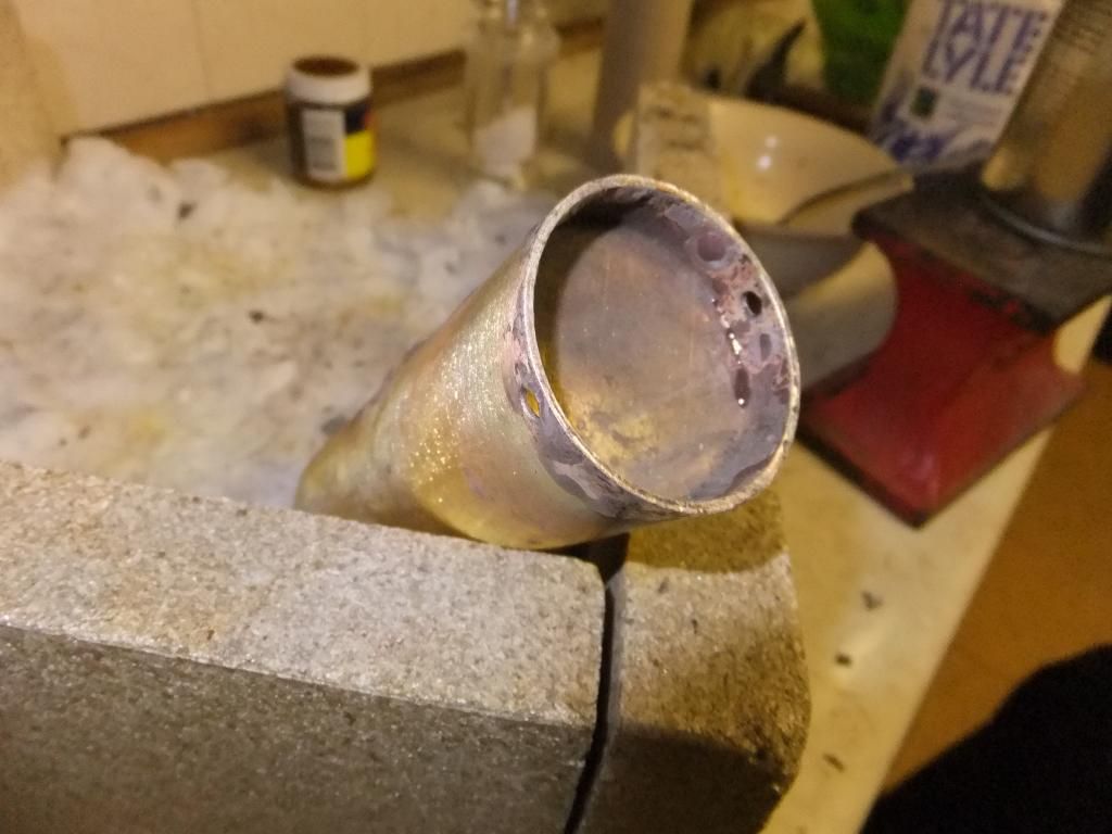
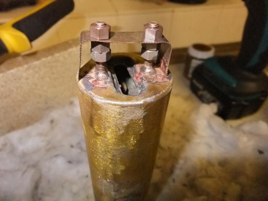
I just found the photos of one that I did a while ago. To be fair once the soft solder is melted and the heat is maintained, the solder acts like a lubricant and the cap literally flies off, if it is going to come off.

Cap just starting to come off.

Image

Image

Image

User avatar
Chris Cairns
Driver
Driver
Posts: 2366
Joined: Mon Oct 29, 2007 7:25 pm
Location: Glasgow, Scotland

Post by Chris Cairns » Tue Sep 10, 2013 9:39 pm

Those photos are brilliant Ace.

The first ones I have seen posted on-line clearly showing how the front boiler recessed cap is fitted. And looking at the inside of that boiler it is the only way to get rid of the deposits stuck to the inside. I have a boiler on my workshop SL3 which still suffers from priming due to a lot of build up inside the boiler which cannot be removed by flushing out with vinegar.

Perhaps when I'm feeling brave I'll try to remove the end cap.

Chris Cairns.

User avatar
ace
Fireman
Fireman
Posts: 294
Joined: Sun Jul 14, 2013 9:03 am

Post by ace » Tue Sep 10, 2013 11:35 pm

Thanks Chris,

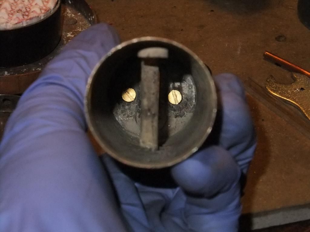
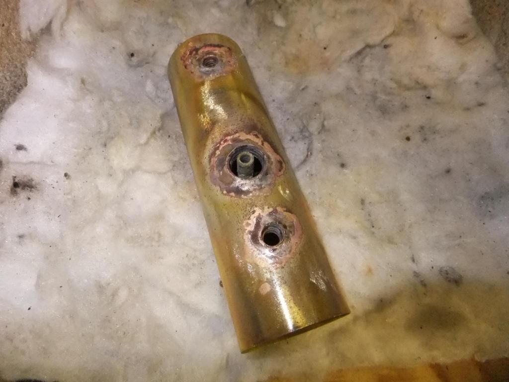
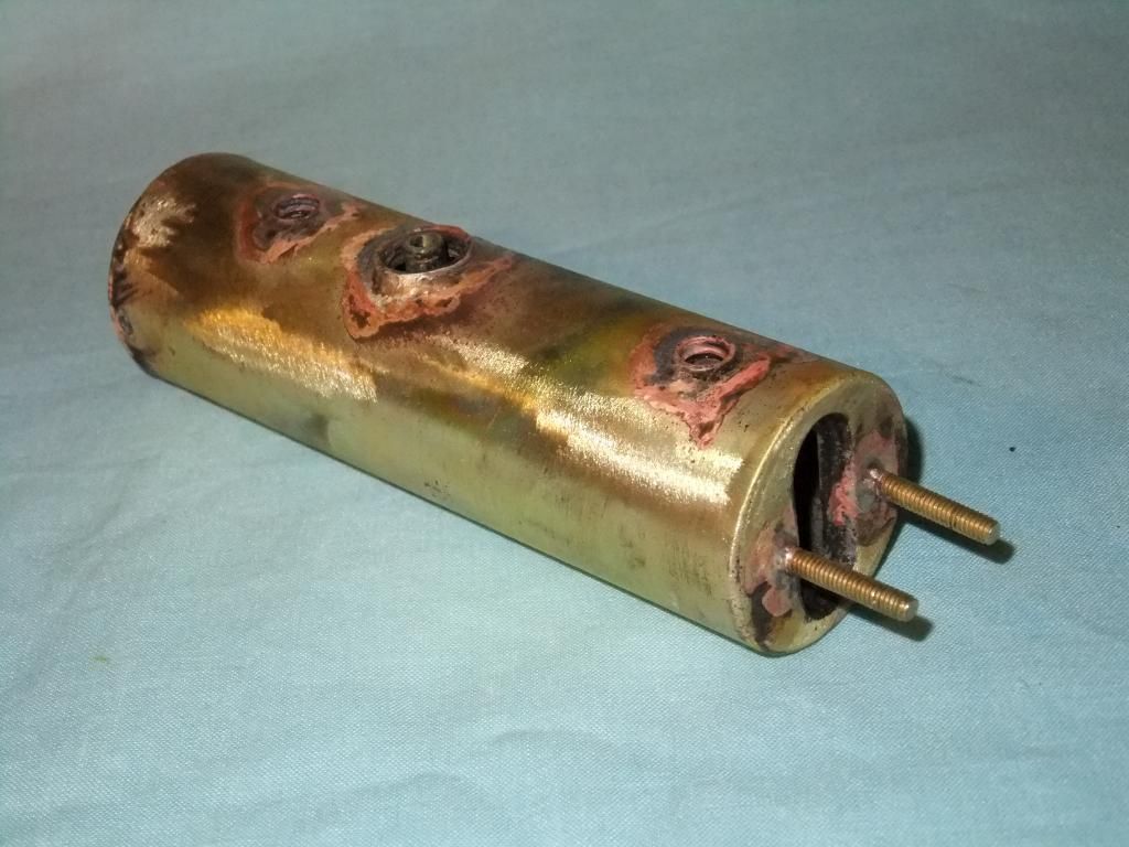
I try to image everything I do, just for my own records really. Here are some images of that boiler going back together. This one is a spare I keep just in case I need one. I try and keep the original boilers with the locos so I can say they are the original ones.

Image

Image

Image

Image

Image

Image

Image

Image

Image

Image

Image

I have just noticed I haven't put the nuts on the end cap of this one. DOH! At least I haven't painted it yet.

User avatar
ace
Fireman
Fireman
Posts: 294
Joined: Sun Jul 14, 2013 9:03 am

Post by ace » Mon Sep 23, 2013 9:24 pm

Hi Guys,

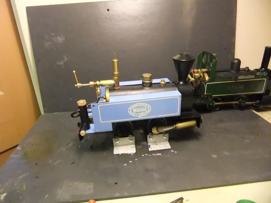
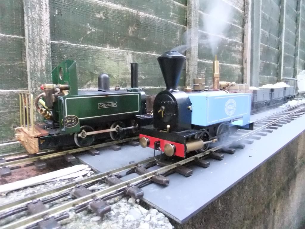
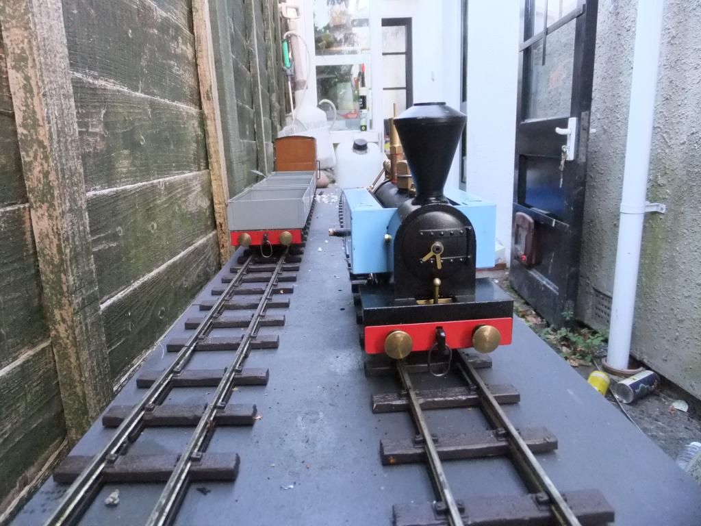
I thought it time for an update. As I have now got well and truly deeper into this project, I have now got a working model of Sir Huffalot. Essentially I have put him together to get some use out of the upgrades and see if my little tweaks and new parts all work together. After all I want Sir Huffalot to live up to his name. :)

First a few hours running in on the rolling road

Image

Then a quick run light

Image

And finally coupled up to a small train for some pulling tests

Image

Image

And finally a video.

<object width="800" height="600"><param name="movie" value="//www.youtube.com/v/EP34cBjIy_w?version=3 ... ram><param name="allowFullScreen" value="true"></param><param name="allowscriptaccess" value="always"></param><embed src="//www.youtube.com/v/EP34cBjIy_w?version=3&hl=en_GB&rel=0" type="application/x-shockwave-flash" width="800" height="600" allowscriptaccess="always" allowfullscreen="true"></embed></object>

Basically now I am at a good point to start with the bodywork modifications. A member of another forum and I have come up with a design that we are both going to have. It started out with me wanting a saddle tank engine and after chatting over PM, email and Skype we both come up something that we want. I am going to fabricate the whole project in one go and do the testing on my Sir Huffalot and double up the prototype for the other members model to wear. Both engines will essentially have the same body, but with some subtle differences. You will all have to wait and see what is going to happen! :)

User avatar
Chris Cairns
Driver
Driver
Posts: 2366
Joined: Mon Oct 29, 2007 7:25 pm
Location: Glasgow, Scotland

Post by Chris Cairns » Mon Sep 23, 2013 9:55 pm

Ace,

Good to see that you have got the RWM reverser valve to work OK. Is that an RWM lubricator? Seems to have an excessively long drain screw fitting but I guess it depends where you will fit it into the final version of Sir Huffalot.

Appears to be a far bit of steam leaking from the cylinder to back plate interface - is it possible to put stronger springs on the pivot screws/bolts?

Look forward to Phase 2.

Chris Cairns.

User avatar
ace
Fireman
Fireman
Posts: 294
Joined: Sun Jul 14, 2013 9:03 am

Post by ace » Mon Sep 23, 2013 10:04 pm

Chris Cairns:89511 wrote:Ace,

Good to see that you have got the RWM reverser valve to work OK. Is that an RWM lubricator? Seems to have an excessively long drain screw fitting but I guess it depends where you will fit it into the final version of Sir Huffalot.

Appears to be a far bit of steam leaking from the cylinder to back plate interface - is it possible to put stronger springs on the pivot screws/bolts?

Look forward to Phase 2.

Chris Cairns.
Hi Chris,

Yes it is an RWM lubricator and it does have a long drain. It means I can stow it away in the cab a little further and still have good access. Yes the reverser is almost finished, just a bit more playing around with it to get it right.

The steam leaking was done on purpose, I removed the stronger springs. There is a bloody good reason why, but a clue is in the name. I will say it is so hard to make a model leak when you have so many great parts fitted, you have absolutely no idea!

It may be difficult to see now but when the new body and effects are done on the completed model the steam leak will fit in well. :)

Post Reply

Who is online

Users browsing this forum: No registered users and 1 guest