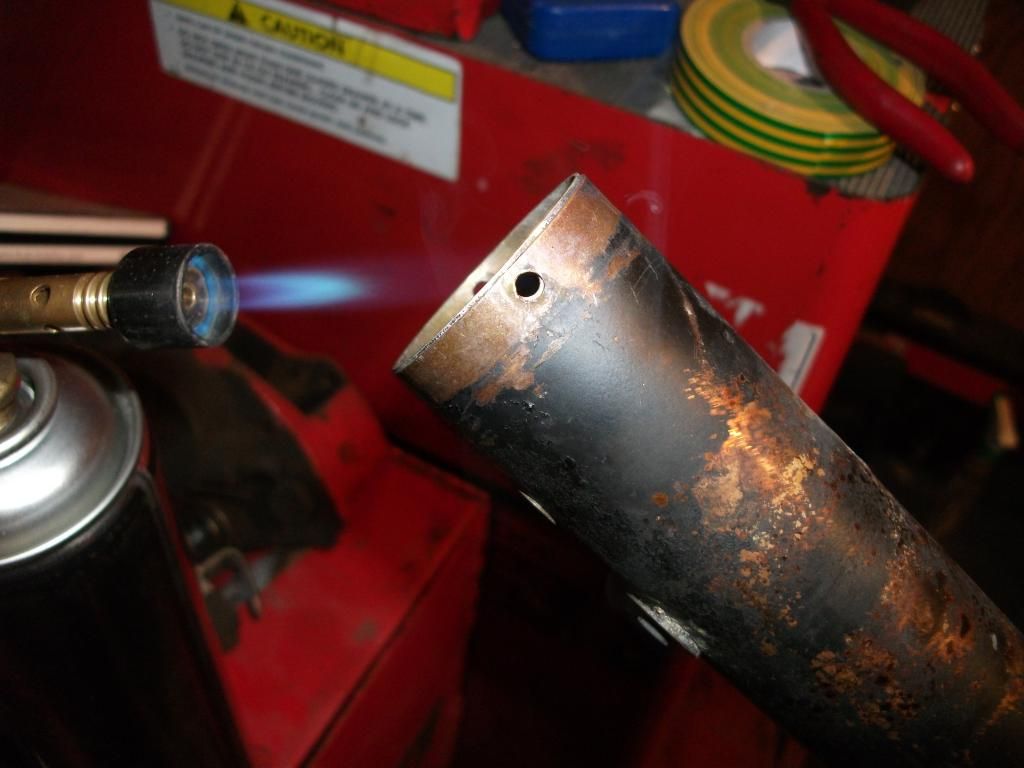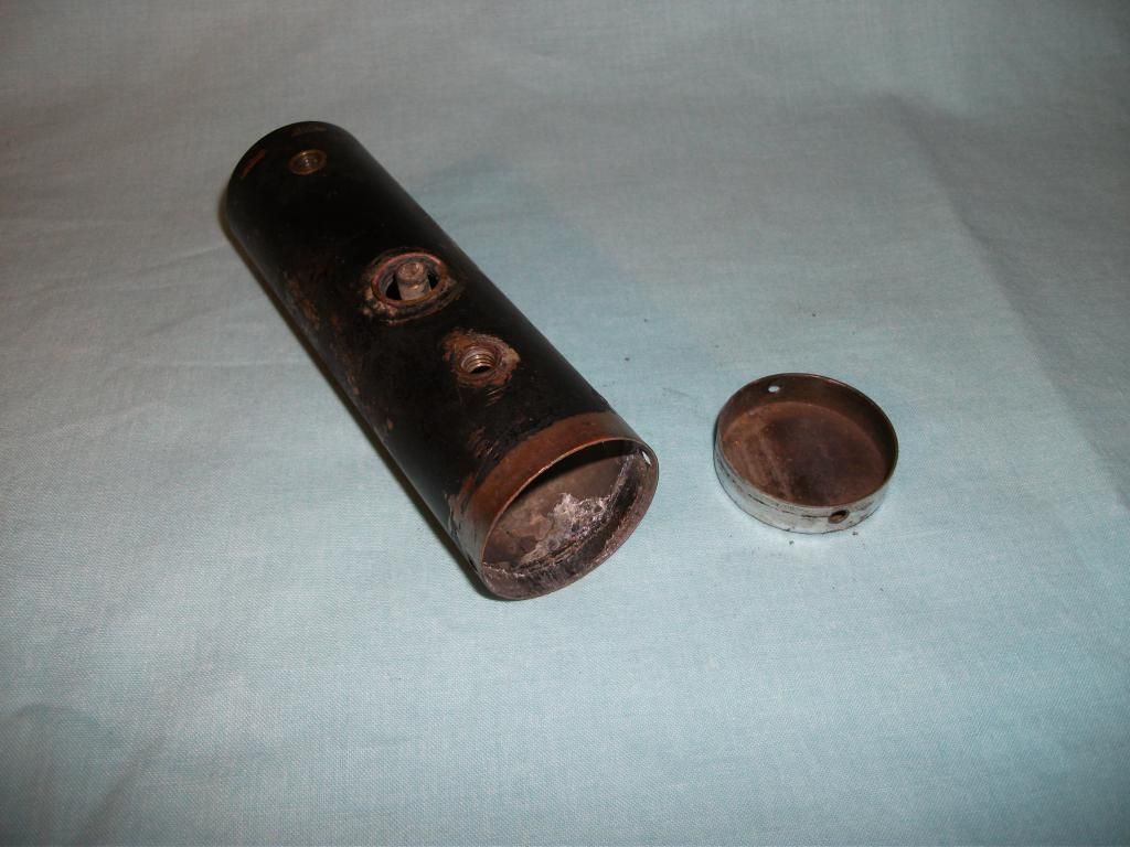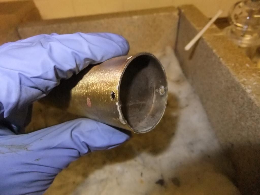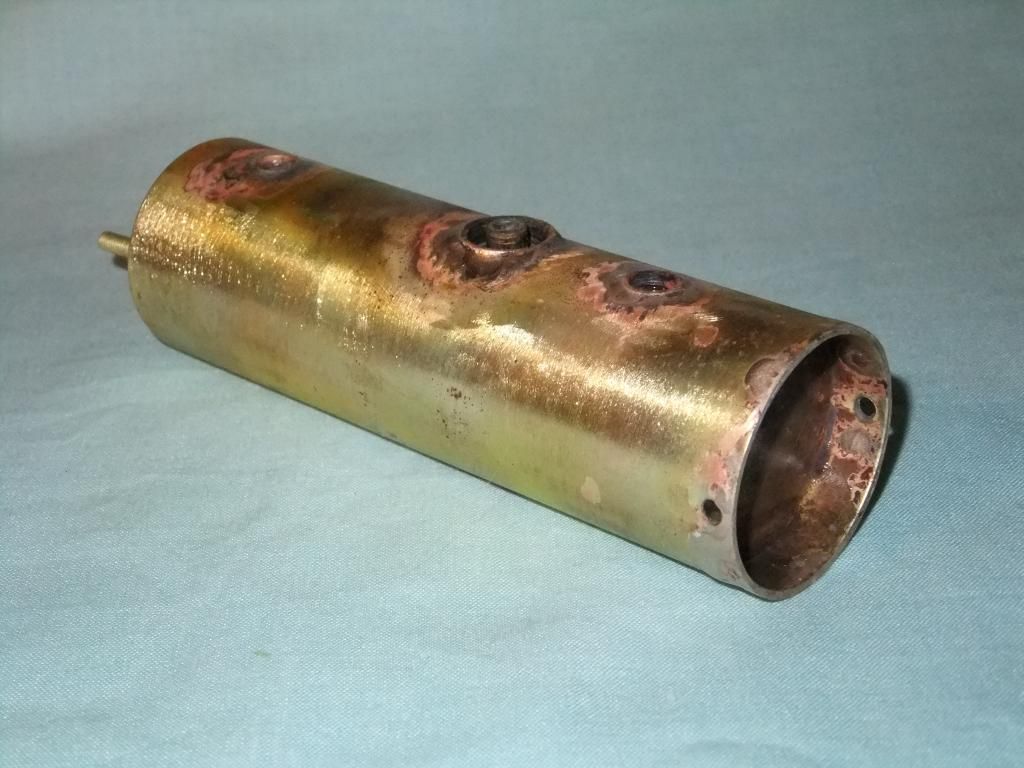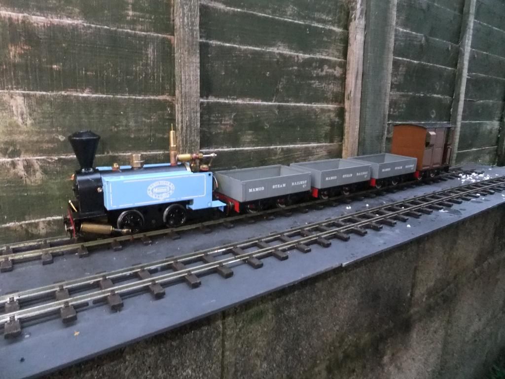

Absolutely Chris, the remainder of the boiler just takes too much away from the solder area. Forget the paint, a blow torch is the only way to go there.Chris Cairns:88305 wrote:As far as I'm aware Mamod used solder paste on all of the SL boilers, and similarly MSS uses solder paste on their loco boilers as well (although probably not enough as owners have found out to their cost).
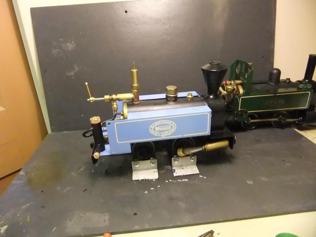
I guess it is all a matter of keeping costs down by having the boilers made in batches rather than the individuality that soldering all the boiler inserts would cause in extra man hours. That is probably why the current Mamod locomotives are more expensive as the boilers are silver soldered, and the wheel sets & oscillating cylinders are made for (not by) Mamod.
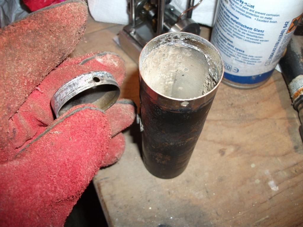
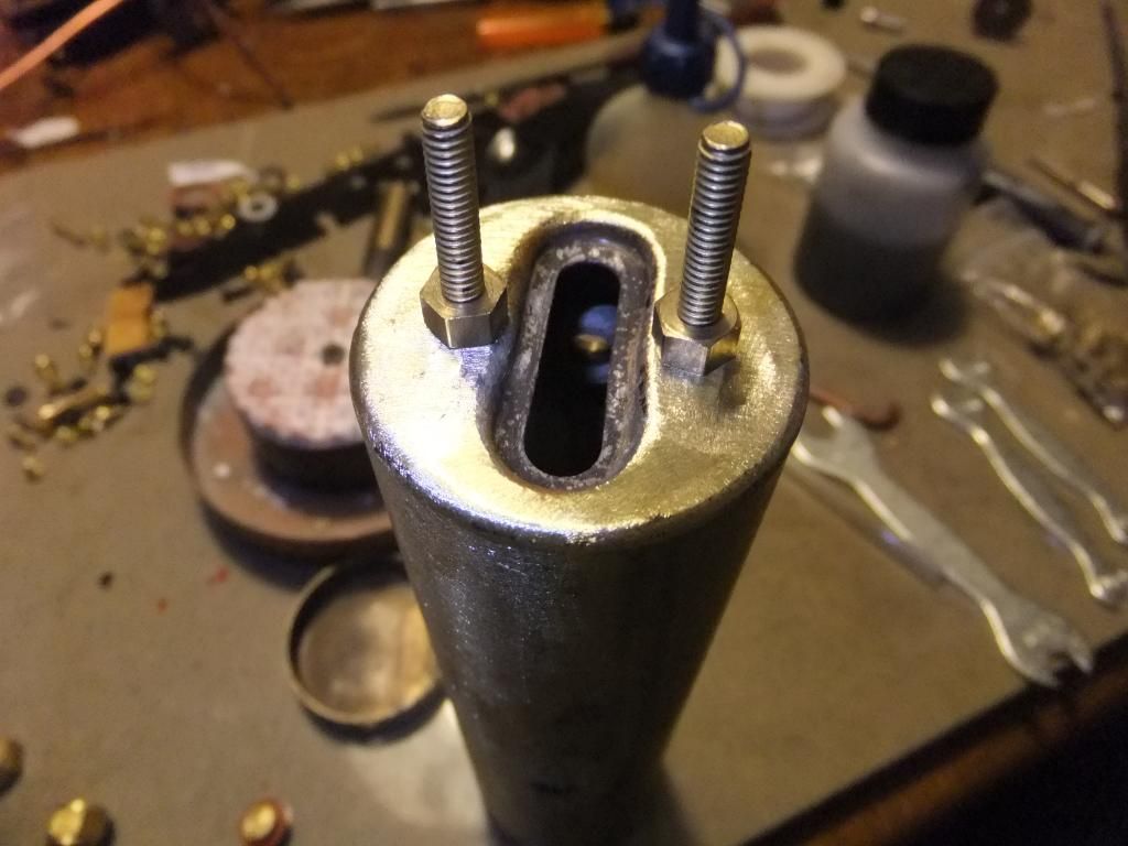
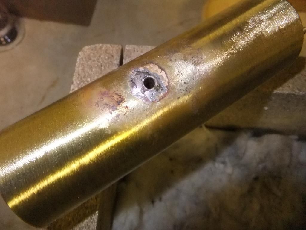
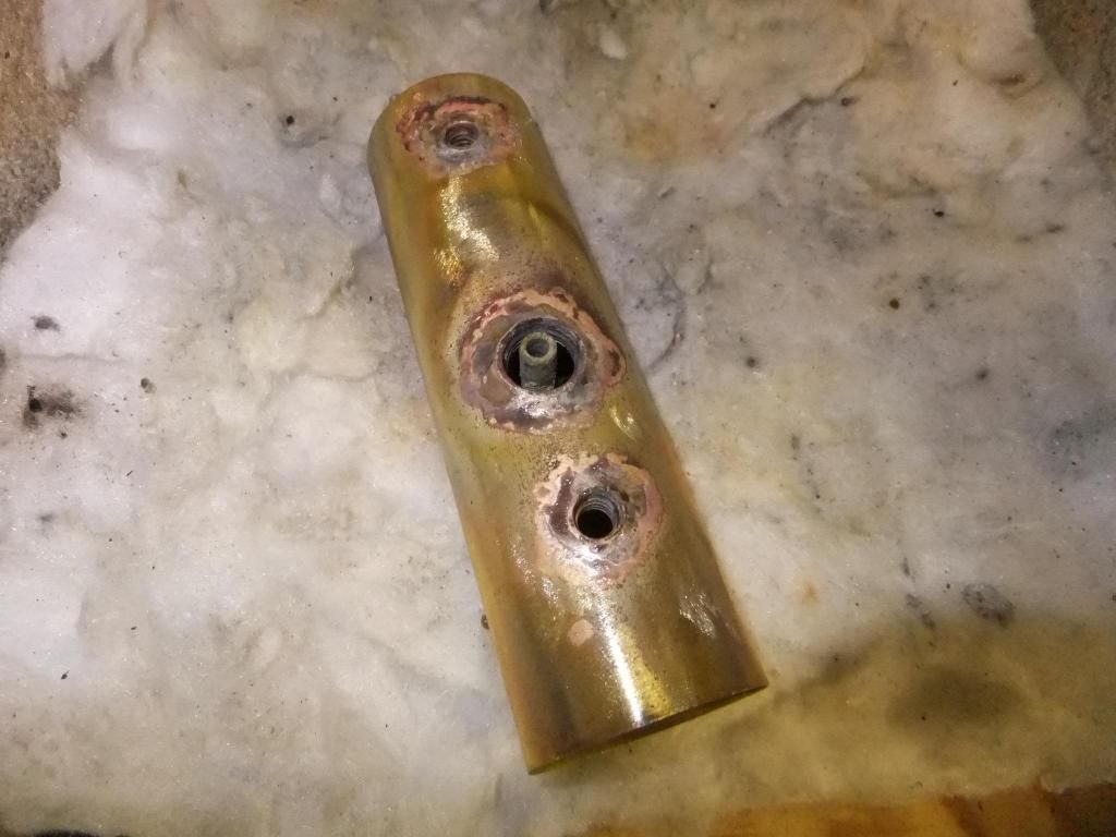
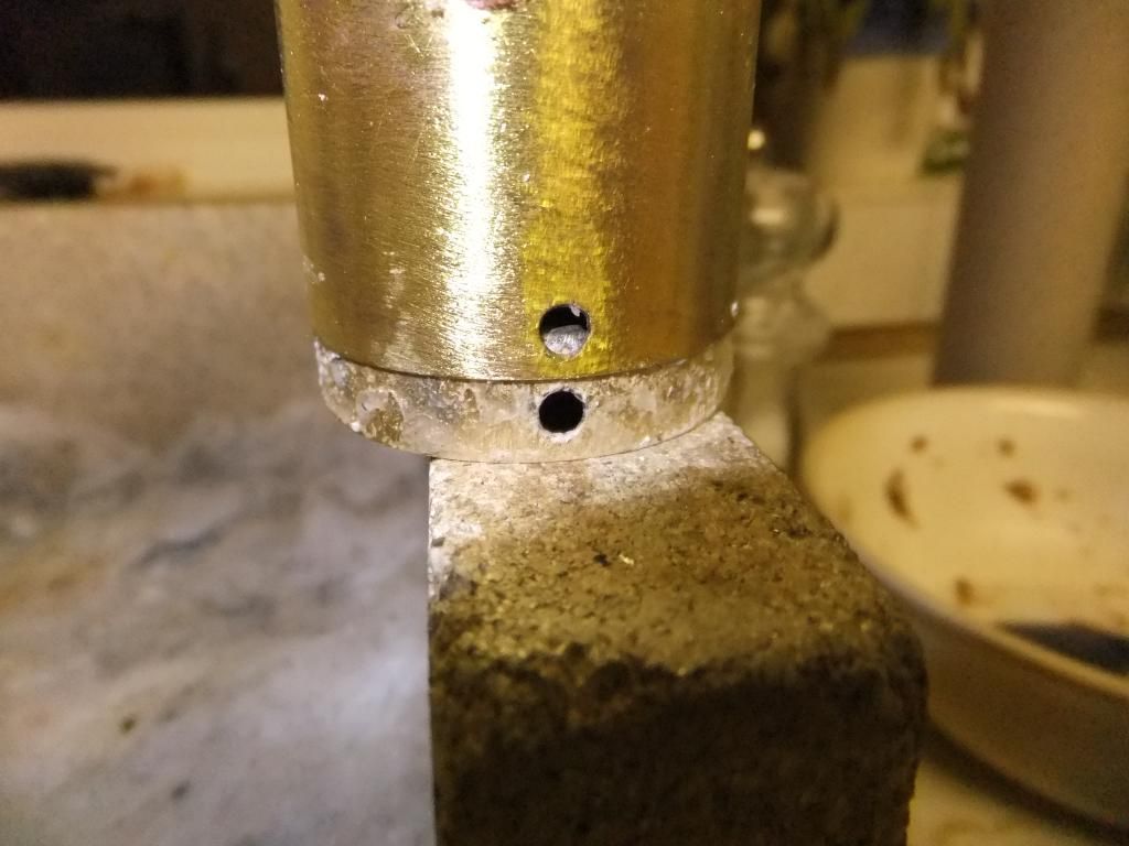
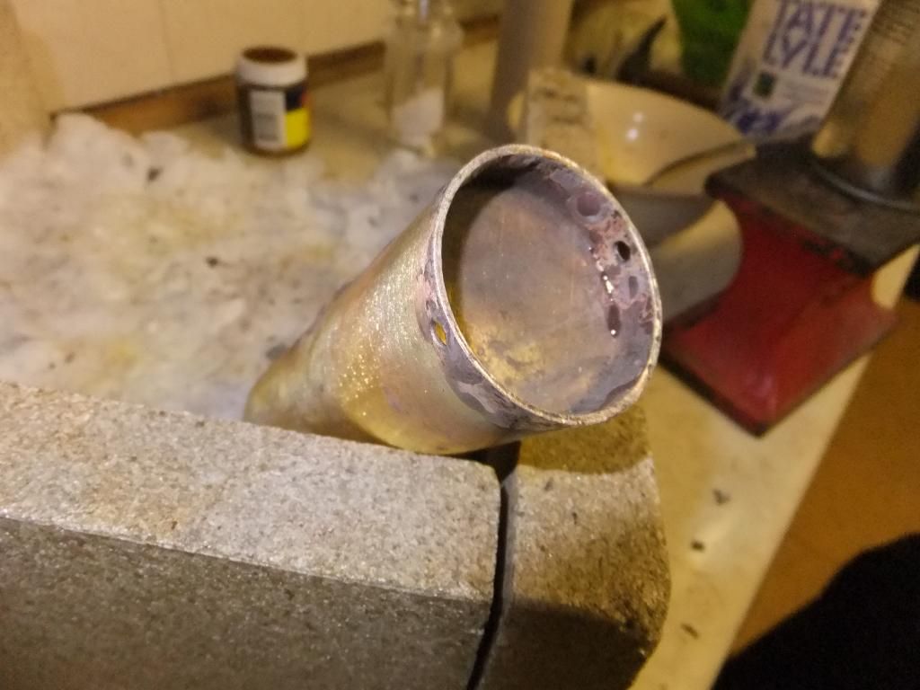
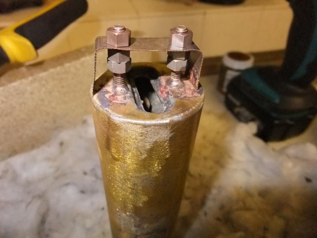
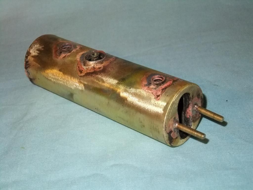
I have a selection of soldering tips for my butane torch but putting one of these into an insert did not seem to get it hot enough to remelt the solder paste so you have to end up damaging the surrounding paintwork by using the open flame option.
Chris Cairns.
Even something as just a little bigger like a roundhouse copper boiler is still too much for a blow torch. The last time I had to solder my Billy boiler, I took it to work wrapped it in the fibreglass matting and used the oxy acetylene torch set. That just heated the area up in seconds. Overkill? Maybe but the job was done neatly and with out fuss.
Having said all that copper is an excellent heat conductor so it is of no wonder the blowtorch struggled.