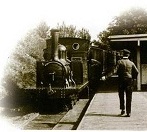

Part of the collection is this Hudson Hunslet. As it's missing most of it's engine, we used it as a brake van on the passenger train, until it's wheel profiles became too worn. The loco's now on display.
I'd always rather fancied doing a model based on this. That went on the back-burner until late 2018.
- IMG_1558 - forum resize.JPG (250.7 KiB) Viewed 3758 times
01/08/19
IP Engineering released a Hudson Hunslet kit in (I think) 2018, for £85. I ordered one in December, and it arrived in January. Thanks to a house move and a number of pre-existing projects, I didn't get round to starting the Hudson until August 2019.
It's an interesting kit, comprising of CNC-milled styrene, cast whitemetal, and 3D-printed parts. All the parts seem to be up to IP's usual good standard.
The loco as standard, is two-wheel-drive. The loco will be made 4WD using the Delrin sprockets and chain at top left.
As it comes, the loco is available in 32mm gauge only (I run 45mm), and the cab and detailing parts are based on No.2207 on display in Blaenau Ffestiniog. As such, the kit will serve merely as a starting point for what I wish to do.
For reference, I'll be be using my own photos and measurements taken at Woodford, and these photos,depicting a much more complete and original machine:http://railsvagabonds.canalblog.com/alb ... index.html
- IMG_5901.JPG (302.93 KiB) Viewed 3758 times
02/08/19
The 3D-printed frames in the kit are a very far cry from that of the prototype. A test assembly with the provided bolts revealed that the extensive stretching of the chassis was to accommodate the motor in it's position between the axles. However, the chassis is lengthened far more than it needs to be - there's roughly ⅝"/16mm of empty space between the rear axle and the end of the motor! I'll have to cut out a chunk of the frames' midsections. Never mind all the other major shape/size discrepancies to fix.. Maybe it's something to do with minimising warpage of the parts during printing; but then I really don't have a clue about such processes.
- IMG_5905.JPG (255.97 KiB) Viewed 3758 times
In any case, these frames can't stay the way they are. I've bolted them together, covering the countersunk holes with tiny washers on this visible side. The round "disks" on the axlebox fronts and on the spring hangers will also be removed, and replaced with more prototypical detailing.
- IMG_5908.JPG (276.68 KiB) Viewed 3758 times
03/08/19
I've never worked with 3D-printed parts before, so I decided to start with a coat of filler primer on the frames, bonnet and whitemetal coupling castings.
- IMG_5912.JPG (217.5 KiB) Viewed 3758 times
04/08/19
To work out just how big a chunk had to be taken from the frames, I first had to fit the worm on the motor shaft, and make another dummy assembly run.
- IMG_5913.JPG (228.97 KiB) Viewed 3758 times
The motor's mounting bracket is a nicely-made part, needing only very little cleanup in the center hole, before it could be used. In the background, a pair of 45mm IP wheelsets was found in the parts box, and the sprockets pushed onto the axles. I wouldn't have been able to make it 4WD on 32mm gauge.
- IMG_5914.JPG (226.38 KiB) Viewed 3758 times
The motor is fitted to it's mount with self-tapping screws. Normally, this would be a trial-assembly to be taken apart and done permanently later, when I'm ready to install the motor - but I hate self-tappers, so I don't want to touch these particular screws ever again. It's a great idea though, fitting the motor with screws rather than glue - makes it so much easier and less destructive to the model, should the motor or worm ever need replacement. Ideally, one would use a motor with tapped holes in it, for mounting with proper machine screws.
- IMG_5917.JPG (230.41 KiB) Viewed 3758 times
After mocking up and accurately re-checking the length of frame to be cut out, I decided to reshape the ends of the frames, the center spring hanger ends, and add a taper to the sides of the axleboxes. Because the printed PLA material is so hard, I ended using the dremel, which was a bit hairy, as the plastic would rapidly start to melt. I got there in the end, and will finish it with emery boards and needle files after the frames are shortened.
The 3" square and a razor saw made for a good job of shortening the frames.
- IMG_5918.JPG (318.58 KiB) Viewed 3758 times
05/08/19
Rechecking the parts again, and I've under a millimeter of clearance from the rear axle to the motor. Including the saw's kerf, about 16.5mm was removed from the chassis length. It's still not perfect, but plenty close enough.
- IMG_5920.JPG (301.34 KiB) Viewed 3758 times
06/08/19
Some ¼" styrene angle was used to join the parts together, taking time to ensure both sides of the frames were precisely identical in length. The holes in the front sides of the axleboxes seem to be cavities in the printed parts, revealed when I removed the un-prototypical "disk" detailing with the dremel.
- IMG_5922.JPG (310.57 KiB) Viewed 3758 times
After etch and filler primers, I could get started on the radiator. There's some blowholes around the bottom of the casting, but that's easy to fill, and the quality is otherwise good. The blowholes were filled with "Selley's Plasti-Bond Bog", and the excess wiped away with a thumb and knife blade.
I quickly realised that the longer I looked at this radiator, the less realistic it became - among many other things, the main issue is that it's thing is a fair bit too wide, as is the bonnet. This isn't much of a problem, though, as I'm thinking that this can be a "might-have-been" 2'6" gauge version, loosely modelled to run on 45mm track. Considering that Hunslet later did an enlarged 2'6" version of the popular 2ft gauge model, I figure what I'm doing sounds reasonably plausible.
- IMG_5924.JPG (250.58 KiB) Viewed 3758 times
Frames bogged up and awaiting sanding.
- IMG_5925.JPG (369.67 KiB) Viewed 3758 times
At this point, I wanted to do yet another mock-up. The bearing holes in the axleboxes needed some careful cleaning out, before the bearings would properly seat. The container of screws was there to counteract the weight of the radiator bending the cardboard "footplate".
- IMG_5926.JPG (237.97 KiB) Viewed 3758 times