Wilberforce goes RC

Discussion of Live Steam locomotives should be located here
User avatar
hussra
Trainee Driver
Trainee Driver
Posts: 872
Joined: Tue Jul 28, 2009 2:06 pm

Wilberforce goes RC

Post by hussra » Tue Feb 05, 2013 9:29 am

As mentioned tangentially in IrishPeter's Load Limits thread, I have really enjoyed running Wilberforce (RH Millie) as a manual loco, but the number of slightly hairy incidents when visiting other lines has convinced me that the time has come when the EHLR needs an RC loco. That, at present, has to mean fitting one of our existing locos.

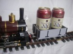
Trying to shoehorn it in without massive changes in appearance... which is made slightly easier by this being a 32mm example rather than 45mm, so more clearance between frames and cab steps. For starters here's Wilberforce in a state of some undress, with the box of tricks under the RH side of the footplate.

Image

Image

This box contains 4x AAA low self discharge batteries, one of the little Planet R4m receivers (smaller than the more common 6 channel ones) and the on/off switch. In these photos it's held on by the buffer beam bolt and a small magnet, but the magnet has now been swapped for a further 8BA bolt up into the footplate. The fake vacuum reservoir is just for show, nothing inside.

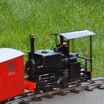
Charging socket goes in a similar position on the other side - just not quite enough room to squeeze it in here. Also that side under the footplate is the whistle servo. Regulator servo is on top of the footplate - one of the little slim wing servos, placed where the driver can stand on top of it in his familiar pose as previously shown here (before RC fitting started):

Image

(I think we may need to slice a couple of mm off the soles of his boots, but otherwise he can stay as-is - in the photo above his feet don't actually quite reach the floor.)

More to come over the coming days - after a successful test on Saturday it's in pieces again and I'm hoping to get the brasswork painted tonight or tomorrow before final reassembly.
Last edited by hussra on Tue Feb 05, 2013 10:42 am, edited 1 time in total.
Richard Huss
in sunny Solihull

User avatar
Gremlin
Trainee Driver
Trainee Driver
Posts: 695
Joined: Sun Feb 08, 2009 2:46 pm
Location: Kent

Post by Gremlin » Tue Feb 05, 2013 9:44 am

That's a neat install, will be interesting to see how the servo looks on the footplate.

User avatar
hussra
Trainee Driver
Trainee Driver
Posts: 872
Joined: Tue Jul 28, 2009 2:06 pm

Post by hussra » Tue Feb 05, 2013 9:53 am

Gremlin:80059 wrote:That's a neat install, will be interesting to see how the servo looks on the footplate.
I'll try and get a photo tonight - it's a Vigor VS-12M 8g ultra thin servo, fixed horizontally on the footplate behind the cab side.
Richard Huss
in sunny Solihull

User avatar
Pendo Pilot
Driver
Driver
Posts: 1897
Joined: Sun Apr 04, 2010 12:24 am
Location: South Staffordshire UK
Contact:

Post by Pendo Pilot » Tue Feb 05, 2013 10:36 am

Lovely work there Richard, looks really good.
Tommy Dodd may have an ARS key but I have a TASS button & a Rope Ladder, just like pirates, except the TASS button bit.

User avatar
williamfj
Trainee Driver
Trainee Driver
Posts: 605
Joined: Sat Nov 20, 2010 9:20 pm
Location: York

Post by williamfj » Tue Feb 05, 2013 12:36 pm

A very tidy arrangement, nicely done.

User avatar
hussra
Trainee Driver
Trainee Driver
Posts: 872
Joined: Tue Jul 28, 2009 2:06 pm

Post by hussra » Tue Feb 05, 2013 8:04 pm

OK, a few more quick snaps. Here's the regulator setup as currently contrived. Various bits need toning down with some black paint.

Image

Image

Here's the fireman's side, showing the cable for the whistle valve disappearing down through the hole in the footplate. (Must make a new, smaller, wooden cab floor.) Servo mechanism in the bilges currently removed for painting of the brass bits.

Image

And here are the bits which fit, somehow, miraculously inside that brass box under the RH side of the footplate (save the charging socket which, as discussed, goes on the other side).

Image
Richard Huss
in sunny Solihull

User avatar
Dr. Bond of the DVLR
Retired Director
Retired Director
Posts: 4485
Joined: Tue Jun 09, 2009 9:43 pm
Location: Suffolk
Contact:

Post by Dr. Bond of the DVLR » Tue Feb 05, 2013 8:52 pm

Wow Wow Wow! Looks grand, where on earth did you get those teeny tiny servos from?
Image
The railway which people forgot
(to build)

User avatar
hussra
Trainee Driver
Trainee Driver
Posts: 872
Joined: Tue Jul 28, 2009 2:06 pm

Post by hussra » Tue Feb 05, 2013 9:14 pm

I got 'em from HobbyKing - http://www.hobbyking.com/hobbyking/stor ... ouse_.html - no doubt other retailers are available also. Also used one of these for the whistle but there's a little more space there.

But have just discovered that my pot of single pack etch primer has gone off :( We shall deal with that tomorrow, now.
Richard Huss
in sunny Solihull

User avatar
IrishPeter
Driver
Driver
Posts: 1400
Joined: Wed Feb 23, 2011 3:24 am
Location: 'Boro, VA

Post by IrishPeter » Tue Feb 05, 2013 10:26 pm

Going RC was something of a problem in the Wilberforce family.... ;)  :D

Really neat installation though!  Very elegant.

Peter in AZ
Traffic Pattern? What pattern? Spuds out; grain in, but cattle, sheep and passengers are a lot less predictable.

User avatar
hussra
Trainee Driver
Trainee Driver
Posts: 872
Joined: Tue Jul 28, 2009 2:06 pm

Post by hussra » Wed Feb 06, 2013 7:18 am

IrishPeter:80086 wrote:Going RC was something of a problem in the Wilberforce family.... ;)  :D
Mmmm yes - the connection had occurred to me when writing the subject line. The family William married into here, on the other hand, was very strongly Evangelical.

Hoping to press on with the painting-of-bits today.
Richard Huss
in sunny Solihull

User avatar
hussra
Trainee Driver
Trainee Driver
Posts: 872
Joined: Tue Jul 28, 2009 2:06 pm

Post by hussra » Wed Feb 06, 2013 4:24 pm

Today's painting has been much more successful than last night's, armed with a new can of U-Pol Acid 8.

This is the battery/receiver/switch housing, as previously seen:

Image

And here's the equivalent for the other side, housing the charging socket and whistle servo.

Image

Finally, for the sake of completeness, a little cover I made up to go over the regulator servo in hope of deflecting any drips from the whistle resonator. (I also filled in the existing drain hole in the resonator and made a new one pointing forwards rather than aft.)

Image
Richard Huss
in sunny Solihull

User avatar
hussra
Trainee Driver
Trainee Driver
Posts: 872
Joined: Tue Jul 28, 2009 2:06 pm

Post by hussra » Wed Feb 06, 2013 7:03 pm

Whistle servo housing now kitted out. And now the purpose of a couple of the holes in the RH end becomes clear - to allow screwdriver access...

Image
Richard Huss
in sunny Solihull

User avatar
hussra
Trainee Driver
Trainee Driver
Posts: 872
Joined: Tue Jul 28, 2009 2:06 pm

Post by hussra » Thu Feb 07, 2013 11:03 am

Right, a more substantial update. First, here are a couple of "inside" shots - here's the inside view of the whistle side servo housing. Quite a bit of empty space - into which the spare length of cable will disappear later.

Image

And just to confirm that space inside the box containing battery, switch and receiver is very tight...

Image

The regulator servo gains its protective shield.

Image

And here is the driver's side with the battery box in place. We'll figure out where to tuck the spare cable once the driver is in place.

Image

Next the whistle servo/charging socket assembly goes in. Yes, things are tight. The lubricator drain is still operable but trickier than before.

Image

Here's the view underneath.

Image

And then on with the bodywork. The driver still needs his feet adjusting, and a lick of paint on one or two of the slightly-visible cables wouldn't go amiss, but pleased that it's generally relatively inconspicuous.

Driver's side:

Image

Image.

And the other side:

Image

Image

Feels like time to go boil some water.
Richard Huss
in sunny Solihull

User avatar
Gremlin
Trainee Driver
Trainee Driver
Posts: 695
Joined: Sun Feb 08, 2009 2:46 pm
Location: Kent

Post by Gremlin » Thu Feb 07, 2013 11:26 am

I like that all looks very neat as I know there isn't a lot of room to play with on a Millie, excellent job.

User avatar
hussra
Trainee Driver
Trainee Driver
Posts: 872
Joined: Tue Jul 28, 2009 2:06 pm

Post by hussra » Thu Feb 07, 2013 1:20 pm

And finally a brief video. Still a little adjustment to do to the regulator linkage, but very pleased all the same...

<object width="853" height="480"><param name="movie" value="http://www.youtube.com/v/clsp7yViu7I?ve ... ram><param name="allowFullScreen" value="true"></param><param name="allowscriptaccess" value="always"></param><embed src="http://www.youtube.com/v/clsp7yViu7I?ve ... n_GB&rel=0" type="application/x-shockwave-flash" width="853" height="480" allowscriptaccess="always" allowfullscreen="true"></embed></object>
Richard Huss
in sunny Solihull

User avatar
Keith S
Driver
Driver
Posts: 1627
Joined: Thu Feb 24, 2011 11:44 pm
Location: Canada

Post by Keith S » Thu Feb 07, 2013 5:33 pm

Very tidy. It doesn't change the engine's appearance at all. I like the whistle.

User avatar
hussra
Trainee Driver
Trainee Driver
Posts: 872
Joined: Tue Jul 28, 2009 2:06 pm

Post by hussra » Fri Feb 08, 2013 8:35 am

Keith S:80136 wrote:Very tidy. It doesn't change the engine's appearance at all. I like the whistle.
Thanks - that was very much the hope. The whistle is a DJB one, fitting of which I described a couple of years ago: http://gardenrails.myfreeforum.org/about3258.html
Richard Huss
in sunny Solihull

User avatar
hussra
Trainee Driver
Trainee Driver
Posts: 872
Joined: Tue Jul 28, 2009 2:06 pm

Post by hussra » Wed Feb 20, 2013 9:12 pm

I hope this is the final update here. The regulator servo proved to be inadequately secured. 2x 8BA bolts through the front edge of the footplate, self tapping into the mounting lugs on the "bottom" (front of the loco) of the servo were the first step, supplemented by this bracket. It is attached by the handrail knobs, and holds the servo firmly down on the footplate. So far, so good.

Image

The bracket in place. The driver can still stand on top.

Image

And here's an overall view of the completed (I sincerely hope) installation including driver.

Image

I can see why Victor Isle thought him unfriendly. His mood has not been improved by the alterations to his boots.

Image
Richard Huss
in sunny Solihull

LakeshoreMike
Cleaner
Cleaner
Posts: 32
Joined: Mon Jun 25, 2012 8:05 pm
Location: North East England

Post by LakeshoreMike » Wed Feb 20, 2013 9:46 pm

Thank you for this thread, Richard. You've inspired me to do likewise. I'd been thinking of the receiver and servo in a van with a shaft coming forward to rotate the regulator but was concerned about loss of control if anything derailed and needing an open
upper cab backsheet. The latter doesn't fit in with my plans for one cab.

Part of the aim was to render the loco quickly convertable from radio to manual and vice-versa.

A call to Roundhouse elicited the advice that they put the servo on the footplate and the battery and receiver in a wagon, as with some of their other engines. That didn't appeal and I was heading towards keeping the loco manual only 'til I read the story of your conversion.

Thanks again

Mike

User avatar
LMS-Jools
Driver
Driver
Posts: 1325
Joined: Thu Sep 25, 2008 9:24 pm
Location: Northwest UK

Post by LMS-Jools » Fri Jun 07, 2013 8:46 am

Nice Job. 8)

Post Reply

Who is online

Users browsing this forum: No registered users and 5 guests