
On New Zealand timber tramways loco crews would hang old sacks and even pieces of corrugated iron on the outside of a cab doorway to turn the prevailing wind and weather. I think hanging the canvas outside looks more logical and if it was raining it would prevent water dripping inside the cab.
As to toolboxes I think loco crews would fit them up wherever they could find a place to put them that they wouldn't fall over, but was still handy to get to.
Changing of a Roundhouse Silver Lady - Steamy Clare
-
tom_tom_go
- Driver

- Posts: 4824
- Joined: Wed Feb 23, 2011 3:08 am
- Location: Kent, UK
- Contact:


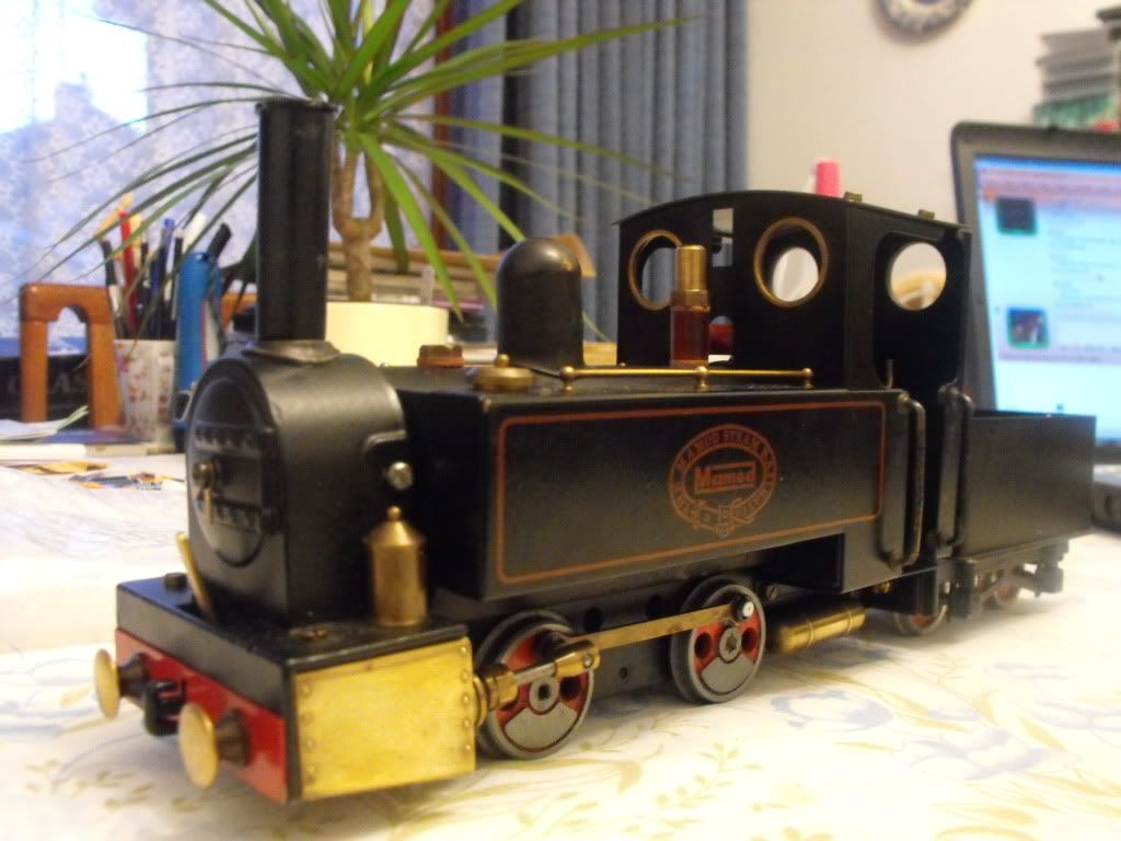
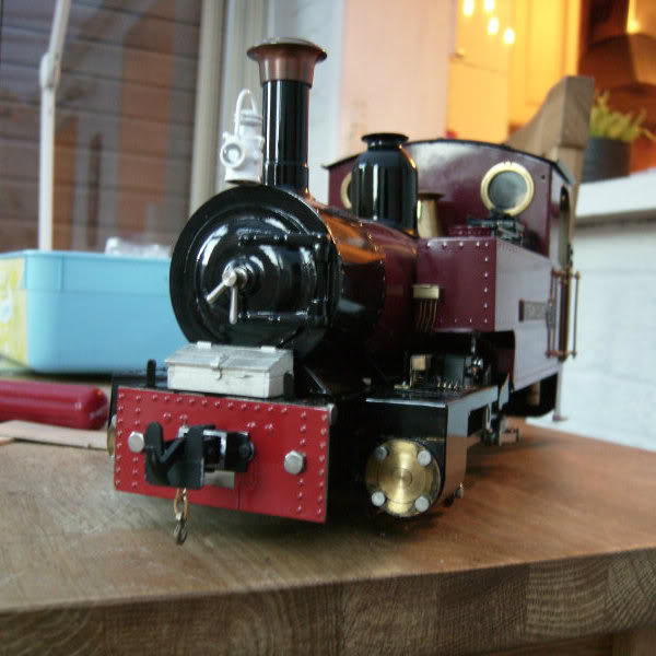
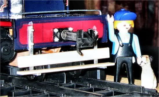
I fear your toolbox would block access to the ashpan and therefore prevent it being ashed out easily. Also, muck from the footplate would probably run straight into it. Best way of hiding the drain screw is probably painting it with some black paint. Or maybe put something like a steam brake cylinder over it, they are sometimes found under the cab. The sheet over the cab side is quite prototypical though, I've seen pics of them on Isle of Man locos for a start
"What the hell is that?"
"It's a model icebreaker sir."
"It's a bit big isn't it?"
"It's a full scale model sir....."
"It's a model icebreaker sir."
"It's a bit big isn't it?"
"It's a full scale model sir....."
Apart from a rolled up tarpaulin on the other side, the one that is down needs to be tied off, otherwise it will just flap around in the wind.tom_tom_go:75751 wrote: A rug tied up on the other side will look good.
In terms of hiding the lubricator drain, just paint it black and mount the lubricator a bit higher so it doesn't protrude as far.
The drain plug is a pain to use at the best of times (especially when hot), so it's best not to restrict access to it any more than you have to......
Graeme
-
tom_tom_go
- Driver
- Posts: 4824
- Joined: Wed Feb 23, 2011 3:08 am
- Location: Kent, UK
- Contact:
Thanks for the additional comments.
If I decide to add a steam brake cylinder do I then have to model vacuum braking on the train and wagons or could this just be used for braking on the loco only? I decided a while back I did not want to model vacuum braking as it's just another detail to buy, paint, etc!
My knowledge in this area is very poor so if someone could enlighten me please?
-
tom_tom_go
- Driver
- Posts: 4824
- Joined: Wed Feb 23, 2011 3:08 am
- Location: Kent, UK
- Contact:
As a generalisation.........tom_tom_go:75766 wrote: If I decide to add a steam brake cylinder do I then have to model vacuum braking on the train and wagons or could this just be used for braking on the loco only?
Loco and train brake are independent of each other. A vacuum brake fitted loco would have a steam brake on the loco, which had a smaller cylinder than the rolling stock, as it worked on steam pressure.
Locos without continuous brakes would have either a steam brake if fairly modern, or just a handbrake on the old ones.
Air brakes on a loco are also small cylinders, but they have an air tank and a pump somewhere on the loco.
These links give an overview of vacuum brake systems and air brake systems.
http://en.wikipedia.org/wiki/Vacuum_brake
http://en.wikipedia.org/wiki/Railway_air_brake
Graeme
-
tom_tom_go
- Driver
- Posts: 4824
- Joined: Wed Feb 23, 2011 3:08 am
- Location: Kent, UK
- Contact:
-
tom_tom_go
- Driver
- Posts: 4824
- Joined: Wed Feb 23, 2011 3:08 am
- Location: Kent, UK
- Contact:
-
tom_tom_go
- Driver
- Posts: 4824
- Joined: Wed Feb 23, 2011 3:08 am
- Location: Kent, UK
- Contact:
-
IrishPeter
- Driver
- Posts: 1400
- Joined: Wed Feb 23, 2011 3:24 am
- Location: 'Boro, VA
Usual kit on the Isle of Man and Manx Northern Railway, besides fire irons was:
Tool box - fireman's side (L/H) tank top on the early locomotives; not carried after about 1905.
Rerailing jack - again tank top - right side as the locos are driven from the right, and unlike the tool box it was not too much of an obstruction.. Generally speaking one is looking well ahead so driver on right signals on the left is not a problem. A few are sited on the wrong side to help sighting!
South line locomotives had a small canvas dodger to fill part of the opening in the uper part of the cab. North line engines also had a wooden board to jam in the opening between the rear of the tank and the coal bunker for when it was raining and blowing a gale. They also had a large canvas draught dodger that filled most of the upper part of the cab opening.
I have seen a photo of 'Cale' with the whole of the cab opening on the fireman's side closed in with canvas dodgers and a wooden board in the door. The photo was taken during the big snow of 1895 and she was the lead loco in a three engine snow clearing effort! As the line only had four locomotives that tells yer somehink.
Peter in AZ
Traffic Pattern? What pattern? Spuds out; grain in, but cattle, sheep and passengers are a lot less predictable.
-
tom_tom_go
- Driver
- Posts: 4824
- Joined: Wed Feb 23, 2011 3:08 am
- Location: Kent, UK
- Contact:
While that is generally true, there are a lot of locos that used vacuum on the loco and had no steam brake. This arrangement was used on the standard gauge by some GWR (all?) and LNER locos, and is also used on NGG16 Garratts.GTB:75769 wrote:Loco and train brake are independent of each other. A vacuum brake fitted loco would have a steam brake on the loco, which had a smaller cylinder than the rolling stock, as it worked on steam pressure.
On an NGG16 no vacuum means no brakes (other than the hard-to-use handbrake). The loco brakes can be applied independently of the train brake, i.e. a train can stand in a station with the carriage brakes off and the loco brakes on.
Tony Willmore
Rhos Helyg Locomotive Works: http://www.rhoshelyg.me.uk
Facebook: https://www.facebook.com/RhosHelygLocoWorks
Rhos Helyg Locomotive Works: http://www.rhoshelyg.me.uk
Facebook: https://www.facebook.com/RhosHelygLocoWorks
-
plewsy2105

- Fireman

- Posts: 251
- Joined: Sun Oct 04, 2009 7:28 pm
- Location: home
and some southern locos i.e the Lord Nelson class and the schools classWhile that is generally true, there are a lot of locos that used vacuum on the loco and had no steam brake. This arrangement was used on the standard gauge by some GWR (all?) and LNER locos, and is also used on NGG16 Garratts.
plewsy2105
MHR apprentice fitter
MHR apprentice fitter
-
IrishPeter
- Driver
- Posts: 1400
- Joined: Wed Feb 23, 2011 3:24 am
- Location: 'Boro, VA
The Isle of Man Railway's locomotives had handbakes only until the 1920s when vacuum brakes were added. No.16 had steam brakes when new which was probably a good thing as she used for the heavy Port Erin Boat Trains. In practice, the vacuum brakes were little used, there being no Island rule about using them.
When I first got acquainted with the IMR the usual practice was to use five or six (occasionally seven) car sets and to control them with handbrakes. This was satisfactory as the regular guards knew when to apply the brake - for example, all the way from Keristal/Oakhill bridge to Douglas, and the last mile or so southbound into Ballasalla. Otherwise, the usual drill was for the driver to whistle for brakes and for the guard to wind them down before the loco brakes were applied. This prevented the train bunching behind the loco, and then snatching when the brakes came off. The non-funtioning vacuum brake tended to perpetuate the Manx habit of creeping into stations and accelerating smartly away. Also with the dependence on handbrakes for stopping power the carriage handbrakes were maintained in fairly good condition, with those with the best brakes getting the most use. The same usually went for the locomotives
However...
Towards the end of her time in service No.5 Mona had a suspect handbrake. It took about five turns before anything happened, and even when wound all the way on it was not fully applied. Her regular driver liked to "run them" which was perfectly OK when she was paired with one of the brake carriages with good brakes - F40-44, F45/46 or F49 - but if she was paired with F19/20 (the Peel line regulars) or any of the other wooden framed brake coaches it could result in some 'knicker gripping moments.' I'll leave the rest to your imagination.
These ays they usually run with four or five carriages on the hook and always with the vacuum brakes coupled up. The vacuum ejector basically knocks one carriage off the load an IMR can handle, so they will usually bank 6 coach trains out of Douglas, because if the loco is not steaming well the brakes will start and leak on if the pressure falls below 100psi. In former times they would take 6 or 7 single handed, up the bank, though exceptionally (dry day and a good loco) they would take 8.
One other thing to remember about IMR locomotives is not all of them had steam heating gear. This was fitted in the 1930s, but only those locomotives in regular use through the winter were ever fitted. In phots from the 1950s I have only ever seen photos of the gear fitted to Nos. 1, 3, 5, 6, 11, 13 and 14. I have gotten the general impression for the photographic record that it was fitted only to those locomotives in regular winter service. In the early 1950 this would have been 4/5 locomotives, but by the mid-1960s this would have been one - two at the most as the railcars had taken over the winter skeleton service. The old joke was 'you could have continuous brake or warm feet, or neither if the engine were not steaming well.' The thing to look for is an extra narrow diameter copper pipe running along the left side of the boiler. It is usually a bit mprovized looking!
Peter in AZ
Traffic Pattern? What pattern? Spuds out; grain in, but cattle, sheep and passengers are a lot less predictable.
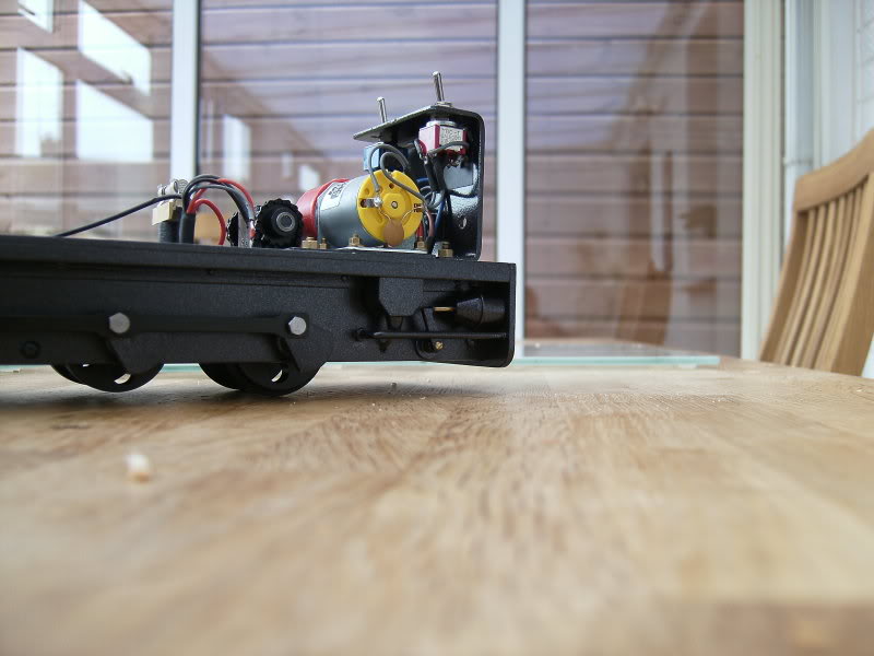
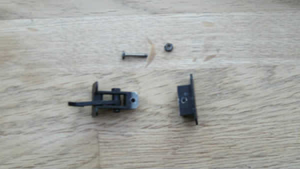
Thanks Tom,tom_tom_go:76453 wrote:here are the pics of the modified coupler you wanted (sorry it took so long!)
Interesting, the W&L couplers have less metal around the pivot than the L&B type.
I shortened the couplers on my locos last week, but only managed to reduce the overall length by 1/8". I ended up fitting side control springs, made out of phos bronze sheet, to keep the shank centred. The spring is the W shaped bit in the photo.

Graeme
Who is online
Users browsing this forum: No registered users and 2 guests