


It is a good book to inspire, however there are little traps if you are not careful, little errors and drawing errors and dimension errors.
It's a better book than many (if not most) model engineering books (and I have a lot of them).Hydrostatic Dazza wrote: ↑Wed Dec 13, 2017 12:24 am It is a good book to inspire, however there are little traps if you are not careful, little errors and drawing errors and dimension errors.
I have many books and subscribed to ME mag since 1985 and also EIM and AME and LLAS and ................. The drawing issues...............bambuko wrote: ↑Wed Dec 13, 2017 11:13 amIt's a better book than many (if not most) model engineering books (and I have a lot of them).Hydrostatic Dazza wrote: ↑Wed Dec 13, 2017 12:24 am It is a good book to inspire, however there are little traps if you are not careful, little errors and drawing errors and dimension errors.
I spotted few omissions as well already, but nothing serious.
There is a Yahoo group https://groups.yahoo.com/neo/groups/Steammodelloco16mm where there is a whole lot of info about corrections etc for Brian's book and design in a file folder called "Steam Trains in Your Garden"
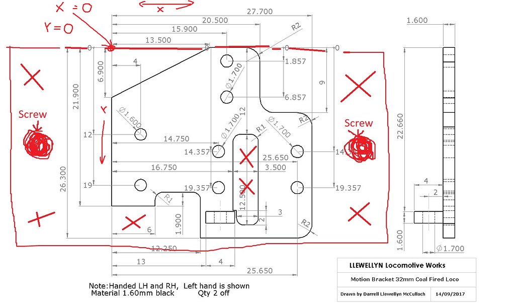
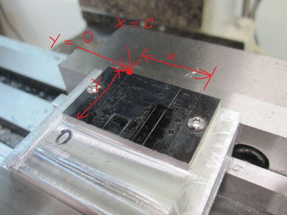
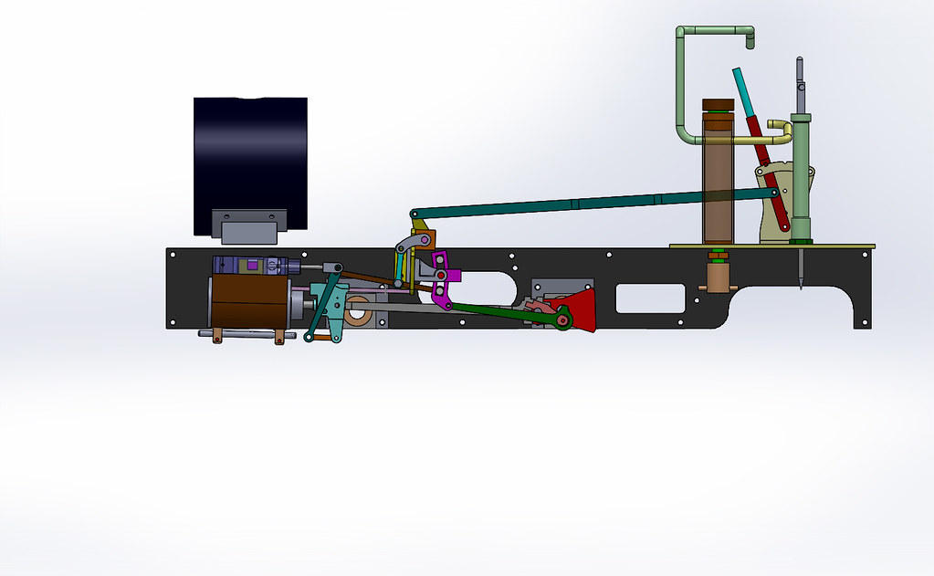
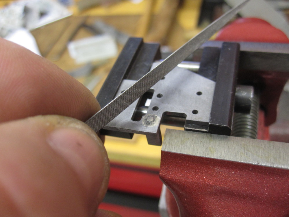
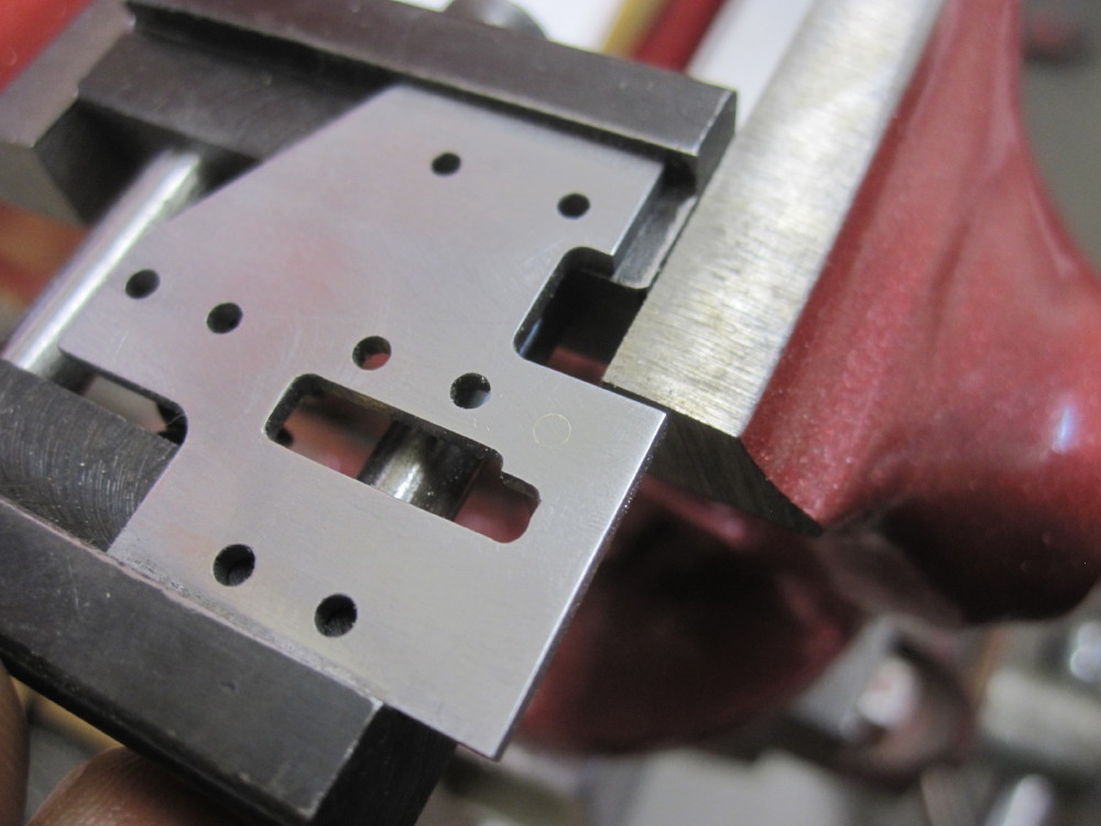
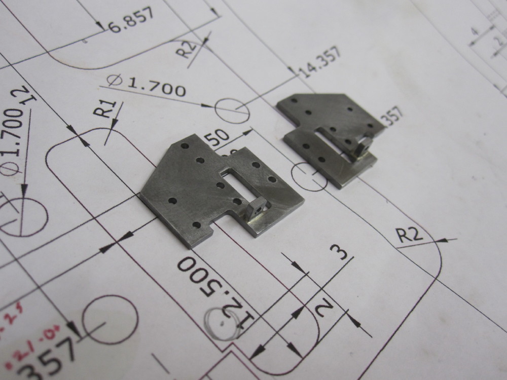
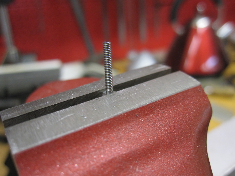
Like yourself I tend to build everything on CAD before cutting metal - easier to sort things out on the screen
BTW would be very much interested in your revised valve gear.
Yes, it is mentioned at quite some length (and again accepted as an error)....the radius rod length does not match the link radius, that is not mentioned in the 16mm file..........etc. Am I right ?
bambuko wrote: ↑Wed Dec 13, 2017 10:02 pm Just to take an arbitrary example from your list of discovered errors:
page 37 in the book showing 82mm - accepted as an error and listed as such in the erratum I have mentioned.
In the tradition of model engineering publications it will never get corrected and will carry on catching unwary
I can see how this occurs as the author of many ME drawings has no commercial motivation to sort/update the master set of drawings. Many times the designer is no longer with us and or concern that has the rights to the drawings does not have time or need to update and they earn a very small amount of coin and there may be a lack the skills to do so, and then many mistakes are the builder's mistakes and then many drawings are privately copied and distributed. So I understand it is impossible to control.
I have latest re-print of the book by Camden and of course nothing got corrected.
But this is nothing new... - model engineering forums are full of these kind of "list of errors" for all designs.
Agreed
There is only one way, and you are doing it the right way (checking it on 3D CAD).
For me it is teaching me a lot, the study of valve gear, it was all good funYes, it is mentioned at quite some length (and again accepted as an error)....the radius rod length does not match the link radius, that is not mentioned in the 16mm file..........etc. Am I right ?
I discovered the 16mm file after I was well into redrawing the loco
Don't get me started on the standard of engineering drawings
I hate the lack of dimensioned GA drawings - the concept seems non existing in model engineering circles...
Hear Hear! and in the instance of the valve gear one can check where the drift in construction may have occurred and or hold tolerances
Usually the designs consist of lot of component drawings with incomplete dimensions with no clue how they go together
Few valve gear designs appear to be correct either (if you read Don Ashton).
Still it doesn't stop us from having fun
Yes, and in the scheme of life, these are all very insignificant things, just get on with it .
I have the code from Oz - didn't know that new one was due... let me know please how different it is (mine is "Issue 1.0 - 2006")
ps totally agree with superheater and slo-mo (and of course RC)
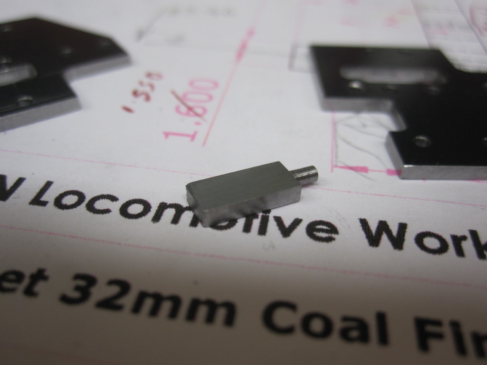
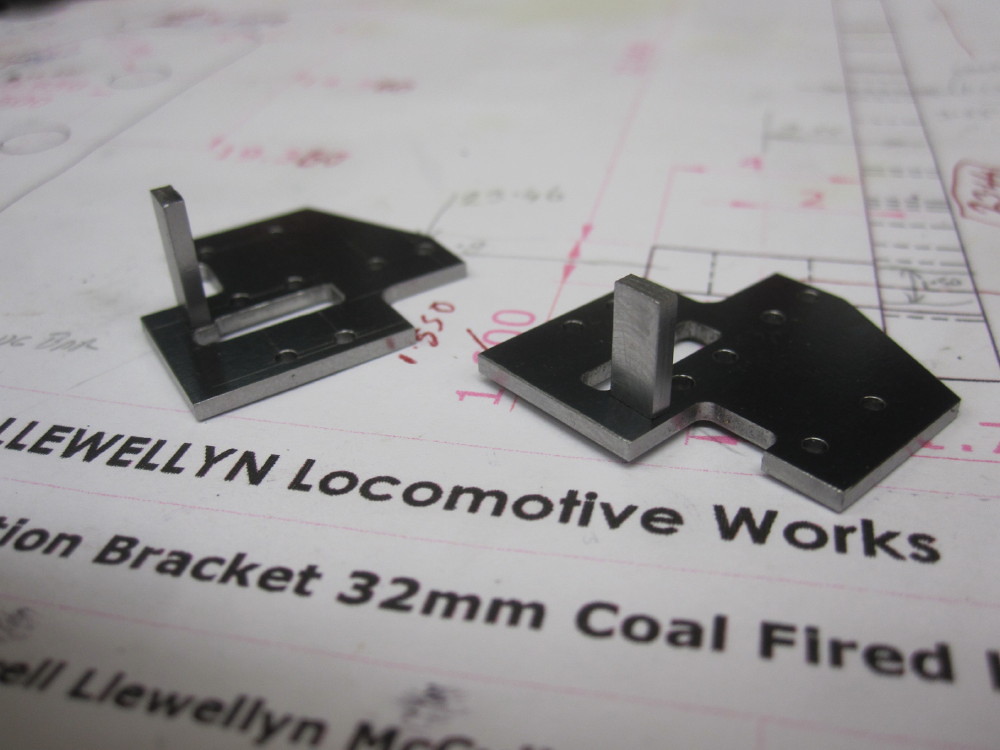
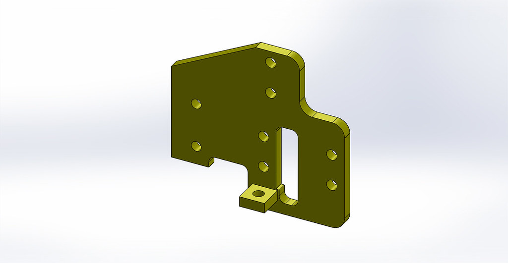
Daan, I do not have B.Wilson's CAD drawings on file, I have the printed 2D and 3D printed drawings fromhis book "Steam Trains in the Garden". Page one of this thread explains that I have created all my own 3D parts drawings myself and I have created the full assembly. But still one can make a mistake. The book is a marvellous inspiration and a good starter, it was heading in the right direction, however there are mistakes, most minor but numerous.daan wrote: ↑Wed Dec 20, 2017 10:14 pm If you have the CAD drawings as a file, you could try if it can be viewed in 3d. That way you can spot these kind of mishaps before you build it. If you only have the plotted version, than that option is gone obviously.
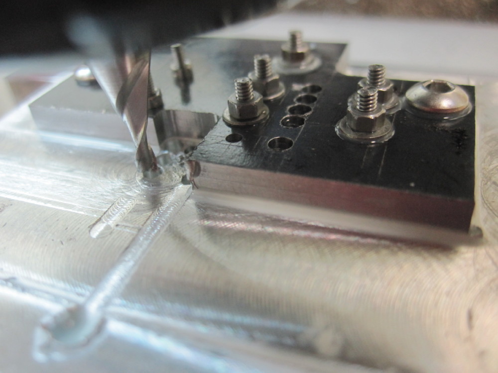
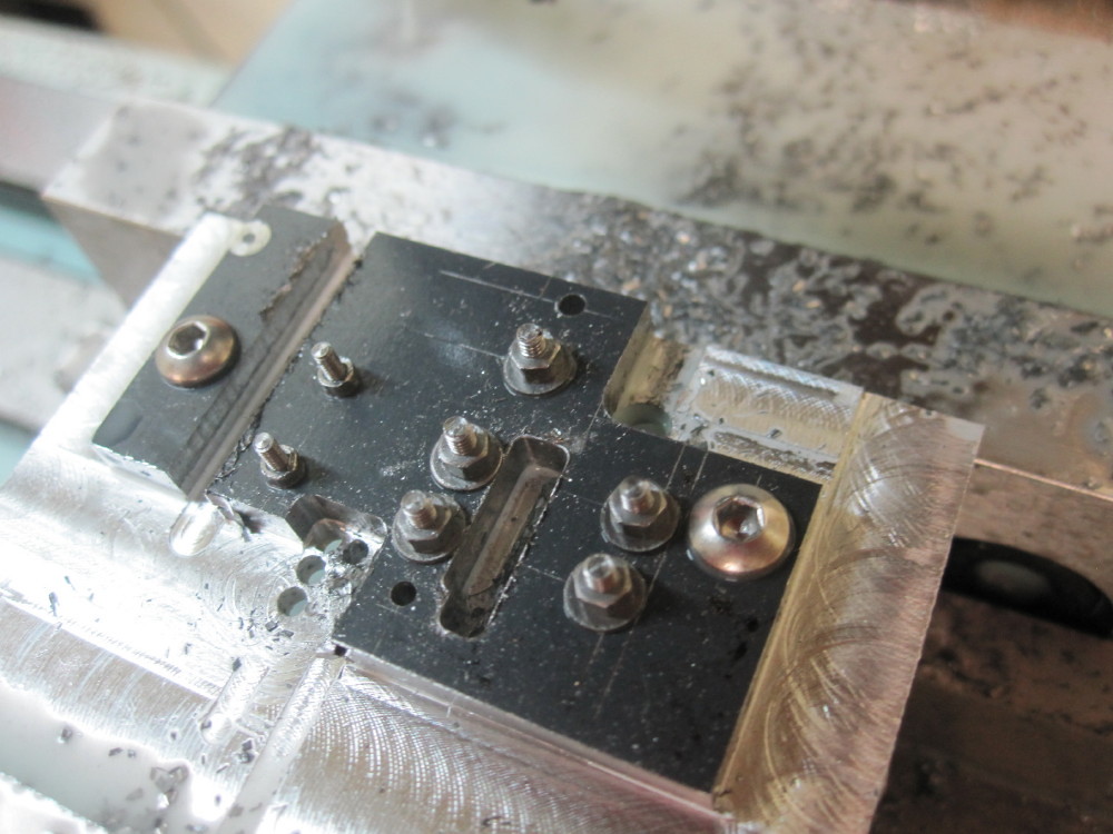
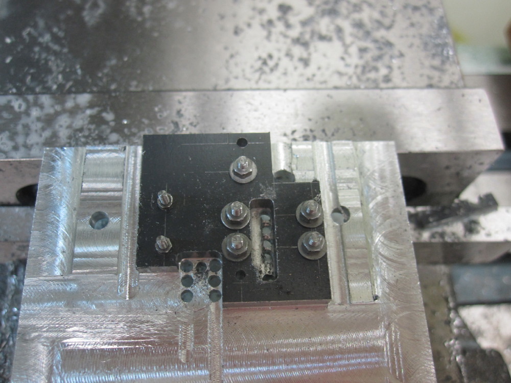
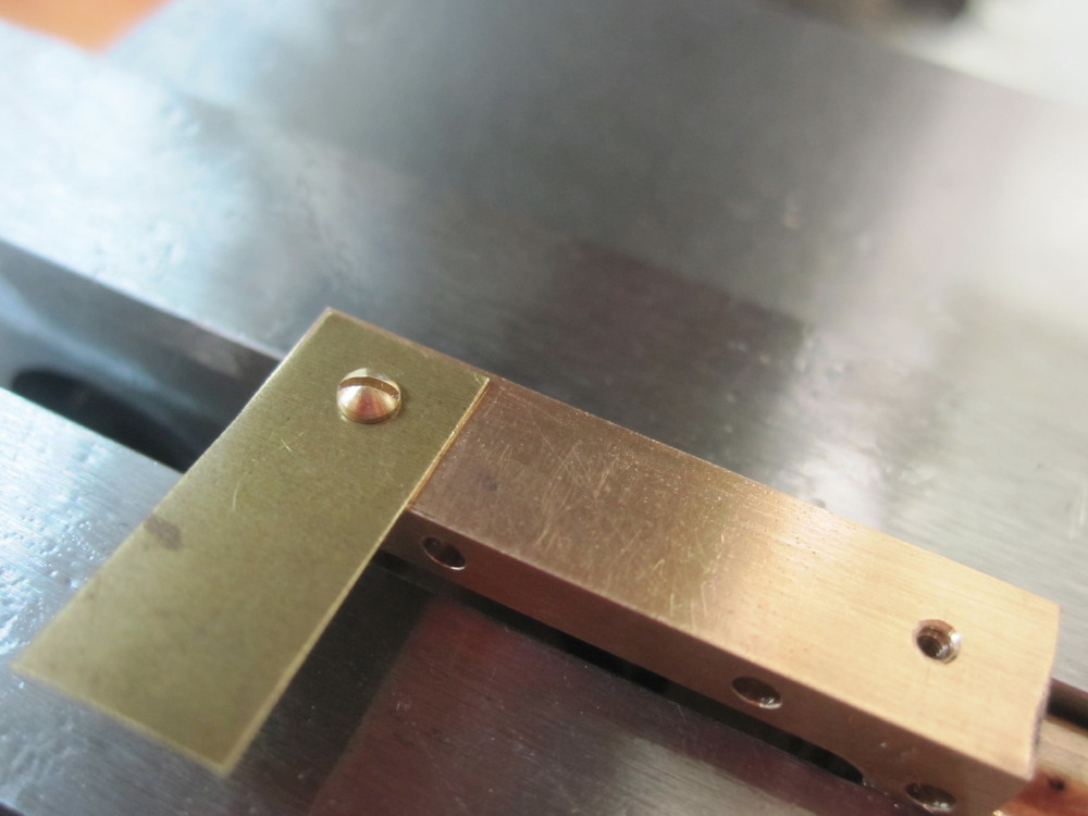
Besides that, very nice and clean work. Looks really sharp!

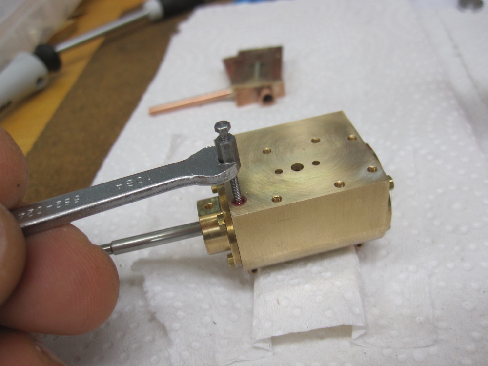
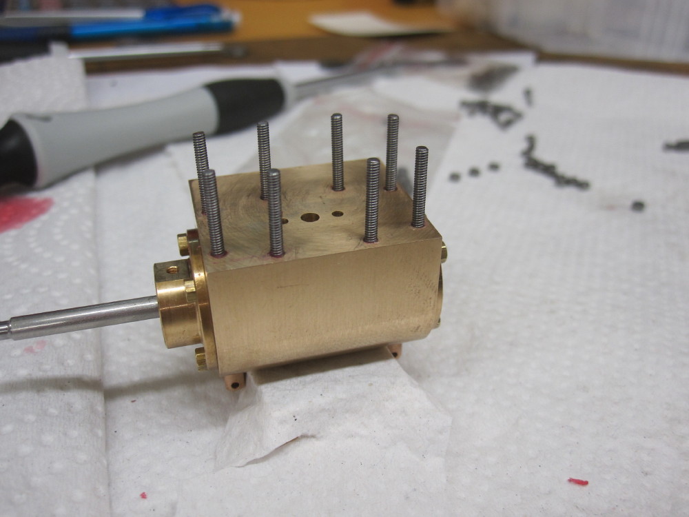

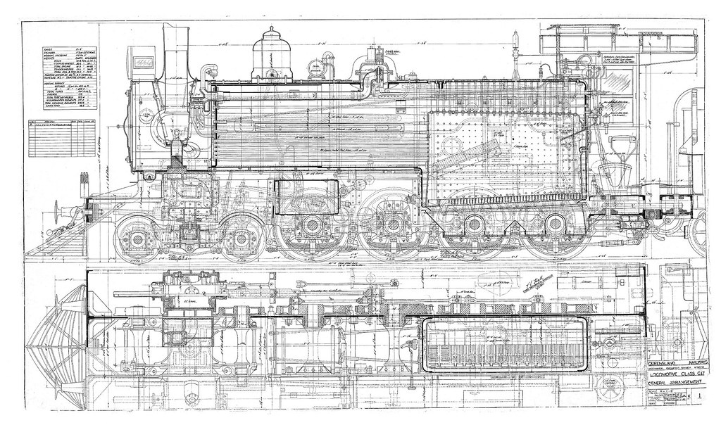
One must admire skilled manual draftsman, when you look at the general arrangement drawings of a loco, it is a joy to gaze upon. The years of toil and application to be in the front group in the drawing office........... respect!daan wrote: ↑Fri Dec 22, 2017 9:07 pm Absolutely great, the cylinder with the studs. Regarding the drawings, I've been technical drawer with autocad for about a year or two a long time ago and I must say that the work is exceptionally dull to do. It is very easy that some faults slip in, like using the former version of CAD drawings instead of the updated ones because the updated one is not filed the right way, or simply because after a few hours CAD it is more a way of sleepwalking..
I did like the oldfashioned ink/ chalk paper version a lot better, that is really artwork to do and because everything takes a lot of effort you really do focus a lot more on what you're doing. To me I really think it's a loss that a lot of this nice handwork is gone.
Users browsing this forum: No registered users and 14 guests