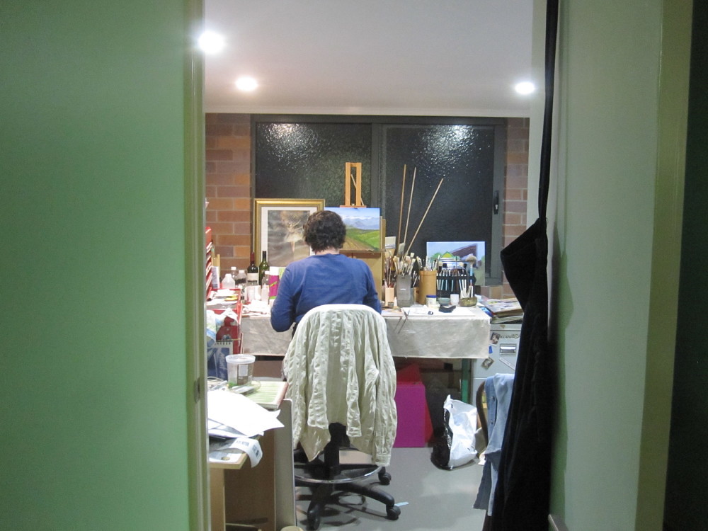
MAM and I had planned a Garden Railway when we did the house and yard rebuild and MAM has a Lady Ann kit waiting for her attention.
In 2015 we had a holiday in the UK for five weeks (my first holiday longer than two weeks for over 30 years)
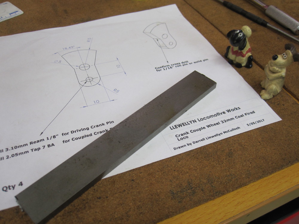
It was while we were in the UK that I picked up Brian Wilson's "Steam Trains In Your Garden. This book motivated to me start my own attempt at a 042 coal fired version of his Eric. For me it has to be coal fired, I feel like I would be cheating to use gas. A bit harsh eh ? ! The book is a good starter, I studied and the drawings. The drawings for coal fired boiler and loco leave some things to one's conjecture, so I think it was best for me to redo all the drawings in 3D CAD and do a full assembly. I have not sorted the final full assembly of my loco, it is still in progress. The procedure is to draw up the chassis and motion etc into a full working and moving assembly. I am self taught in "Solid Works' via the excellent book written by David Murray. I have a new appreciation of technical writing because MAM's profession is a "Technical Writer" which is translating Geek speak to monkey speak (ie: me).
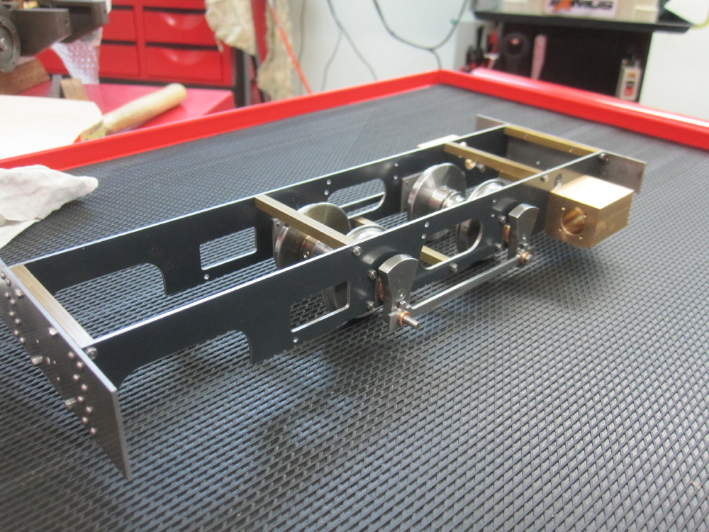
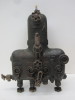
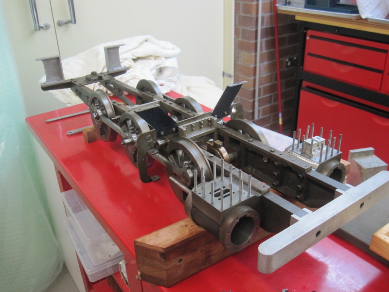
Here is an early draft assembly of # 1. (#1 Llewellyn Loco works build)
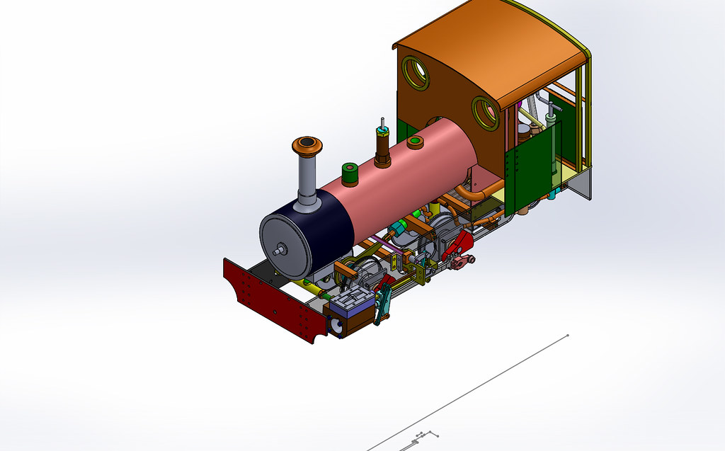
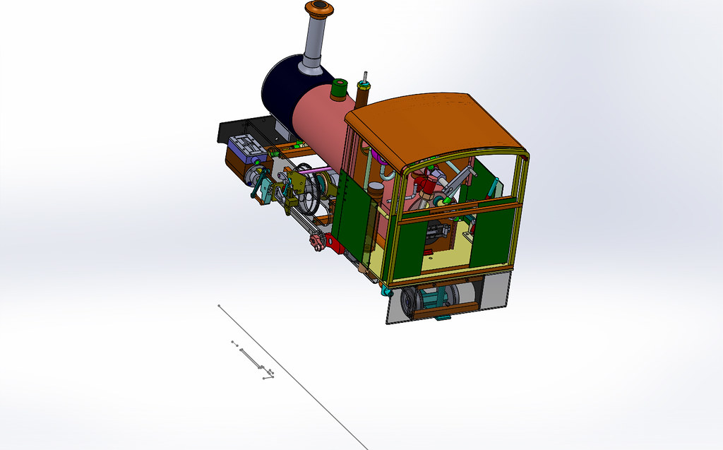
Please note this loco is totally free lance and not trying to represent a real world loco.
It was during this process I discover some errors and some cryptic floating parts locations in the book. More on this as I bring this thread up to the current situation.
The beauty of 3D CAD is the assembly process of the 3D individual parts , to see the fouls, bad alignments etc. Then convert the single 3D part into a 2D drawing for the workshop floor. If some thing is missing, such as a dimension or mistake, this is easily added , or corrected or checked. One can update the part and all the 2D drawings and the assembly are updated as well. SWEET! But, not infallible, errors can creep in so one must still be diligent.
To many this is all so so and well known, but this is my thread so..........................................
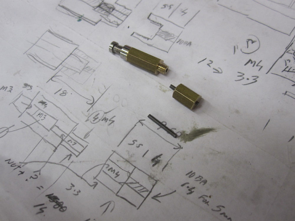
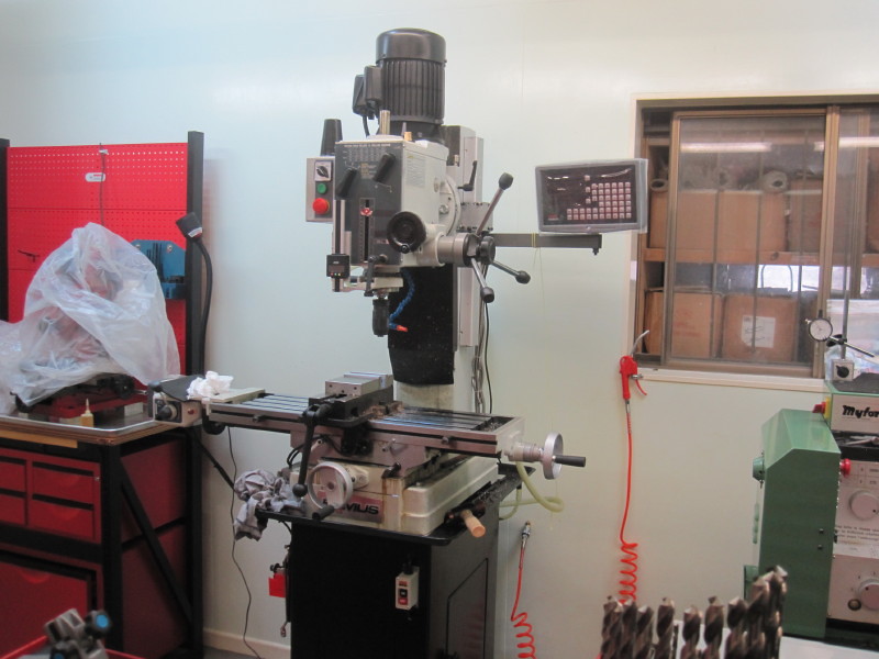
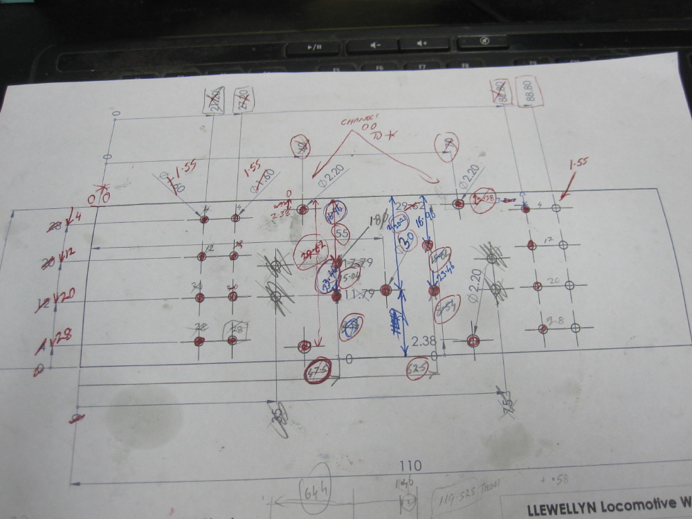
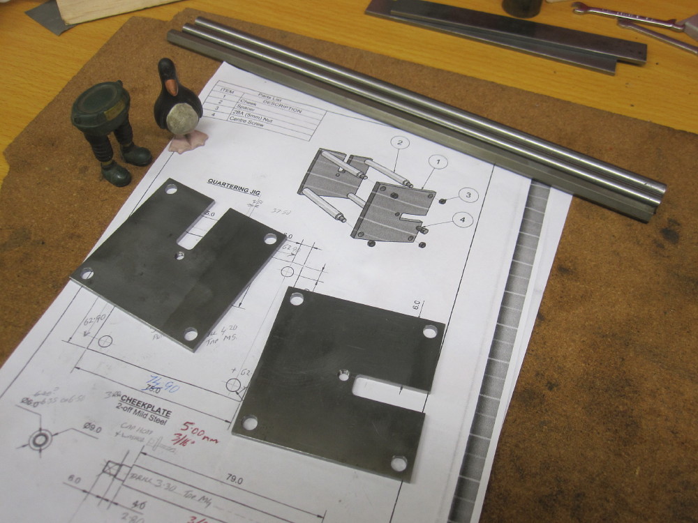
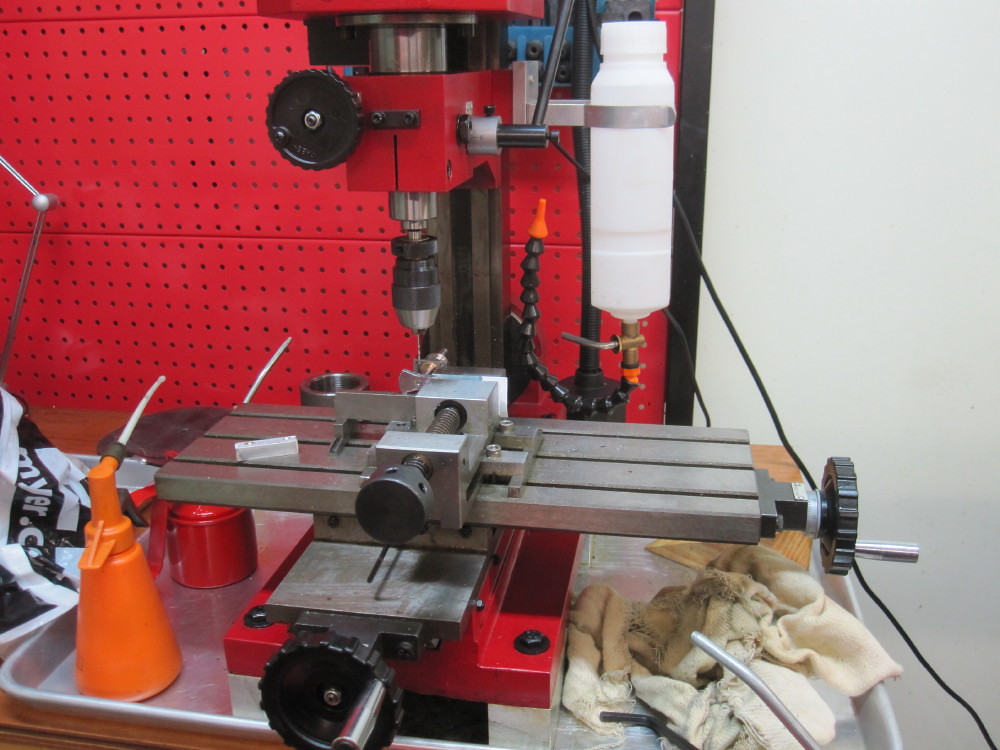
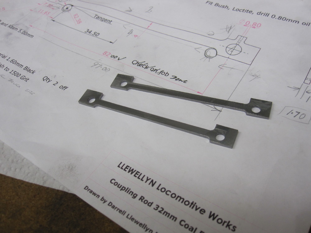
This is my frame plate drawing. Notice I use the ordinate dimension, X and Y = 0 as I am using the digital read out (DRO) on the mill drill. It was my first time with DRO and I am in love with it !
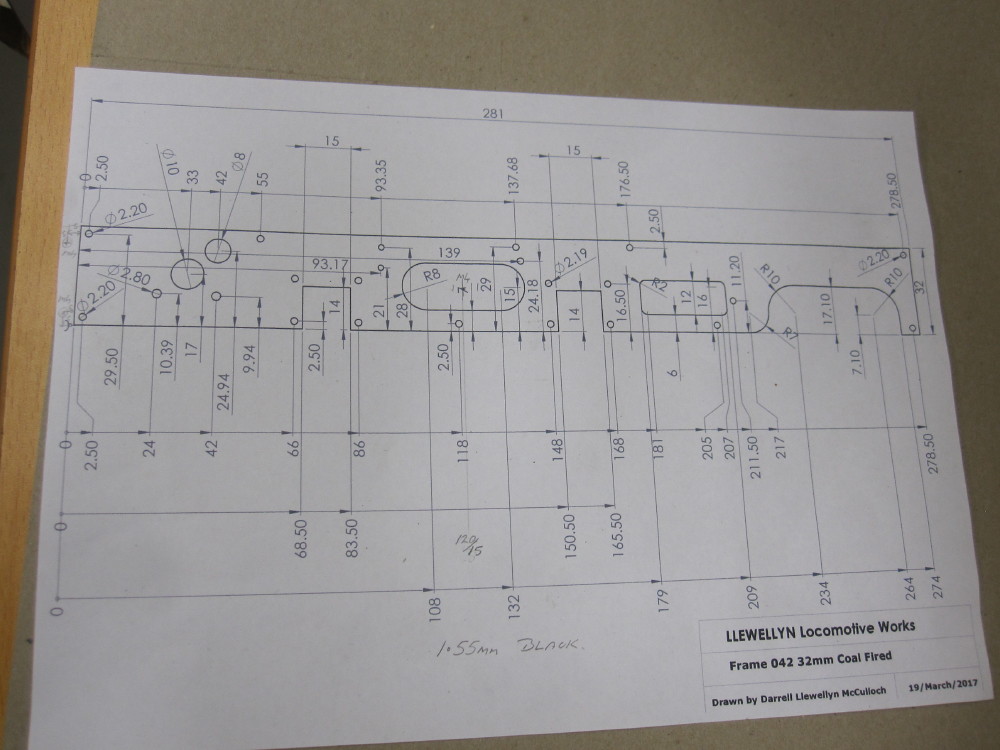
This drawing ends up with notes scribbled on it and alterations and after making the part I edit or update the master set of 2D and 3D drawings. To remove as much as possible silly and lazy errors! Please note, this is not the traditional drafting style and might make many cringe but my excuse is I am self taught, so I let my self off the hook. The main things for me is, that the drawing is proven correct and updated as required. I know many locos have been made from many designers drawings but many mistakes and errors remain for many reasons, both practical and or the builder just moves on, not certain if it is them or the drawing that is the mistake. Just want to get the bloody thing finished .......
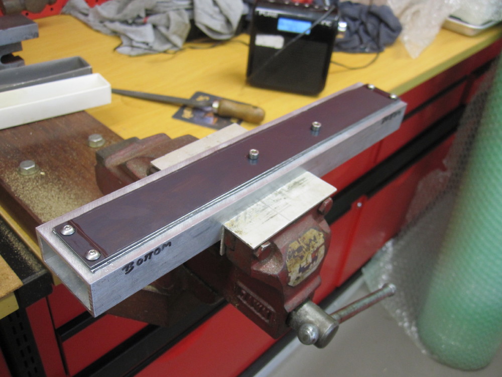
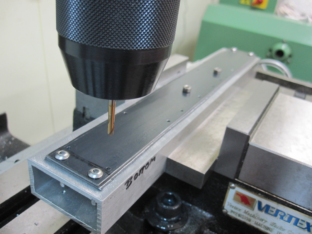
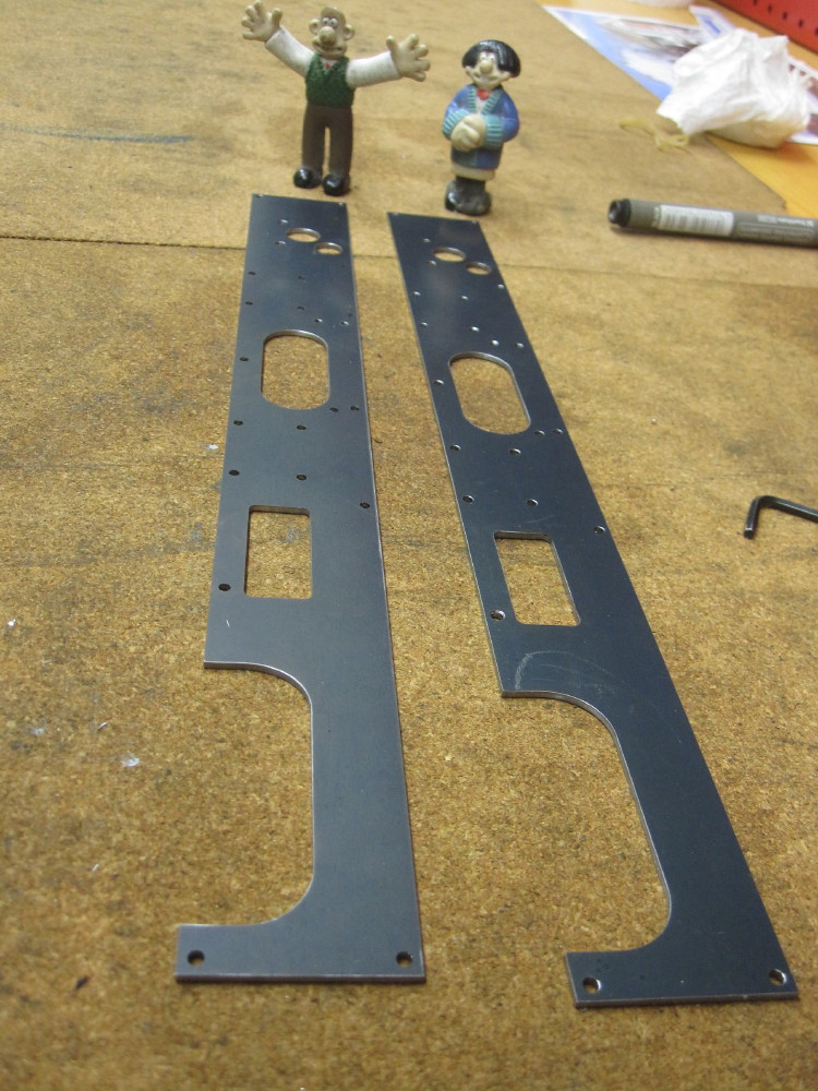
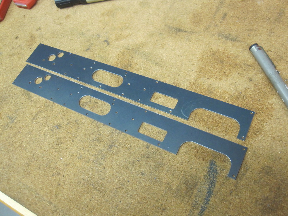
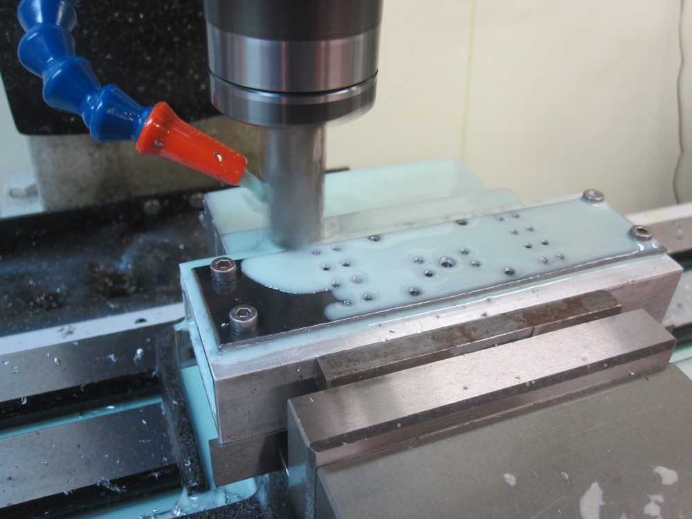
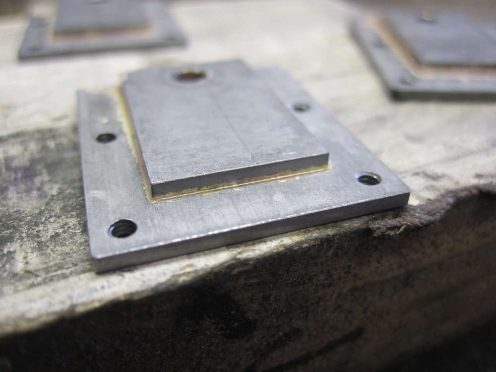
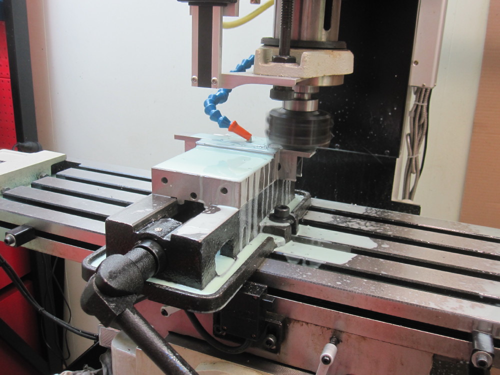
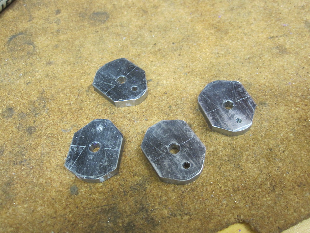
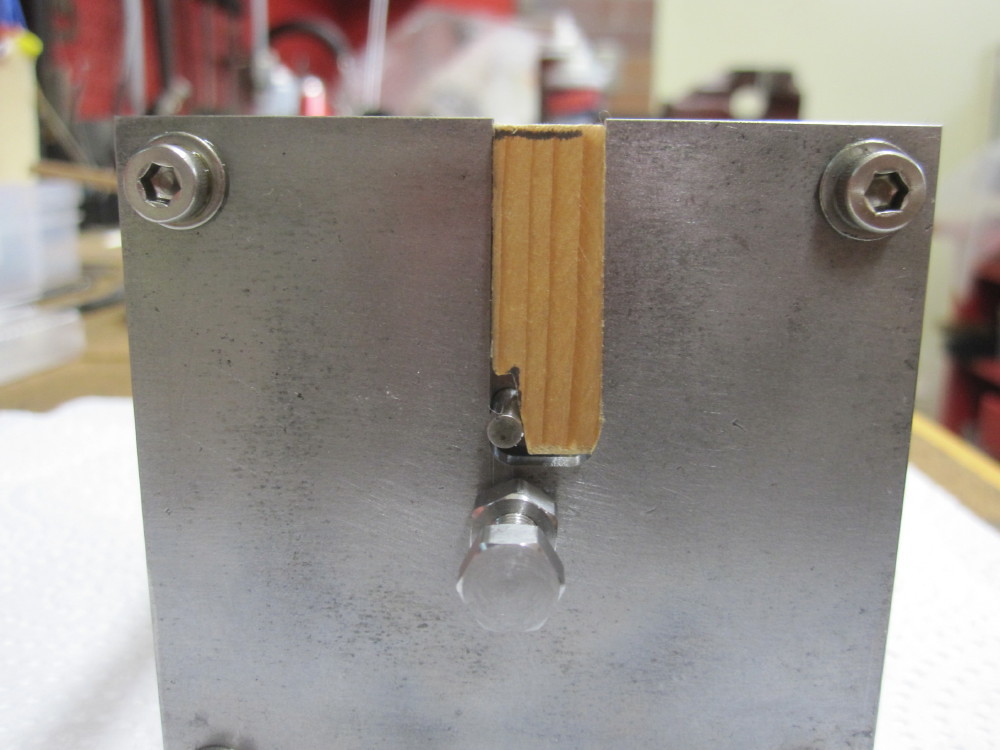
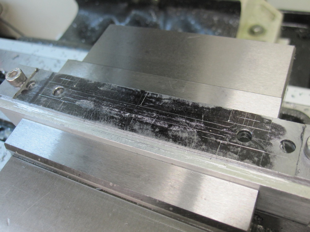
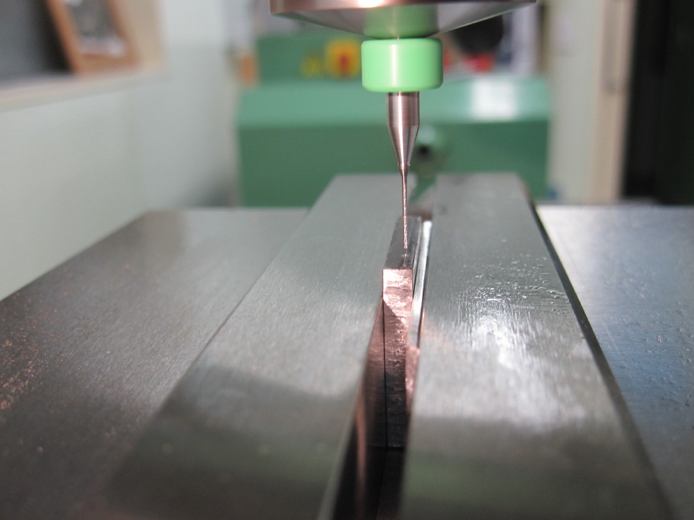
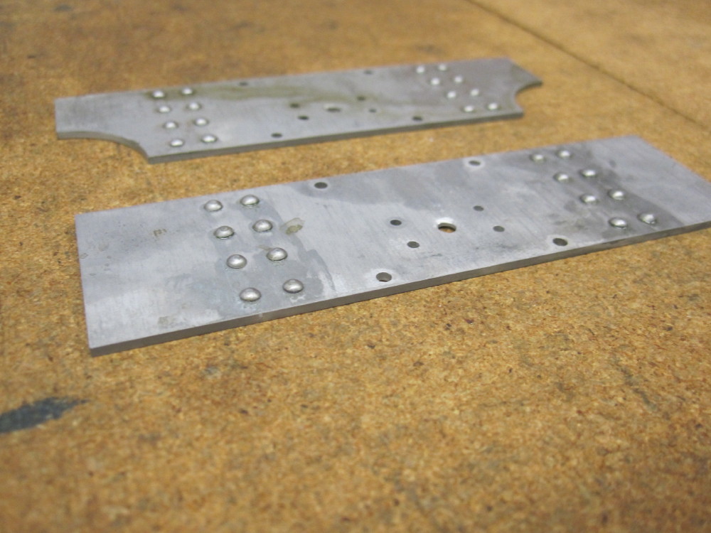
This is both frame plates bolted to a square section aluminum by the excess material on the outside. It is 1.55mm black steel that was bought by MAM at a closing down sale at "Masters". Good lass eh! Black or annealed is used to enure distortion is minimal.
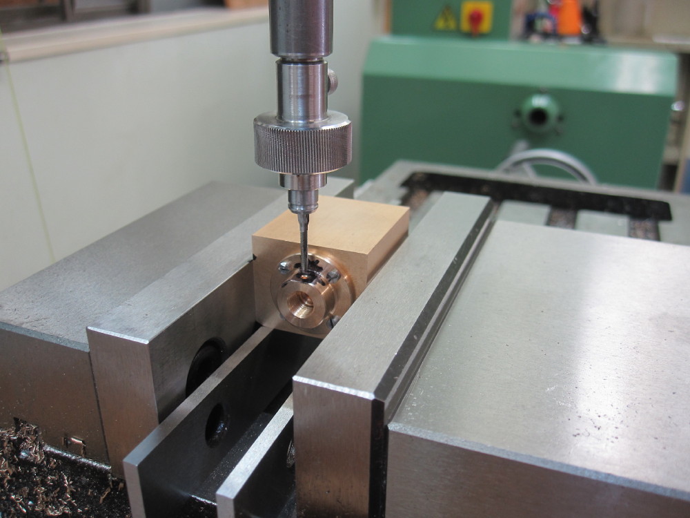
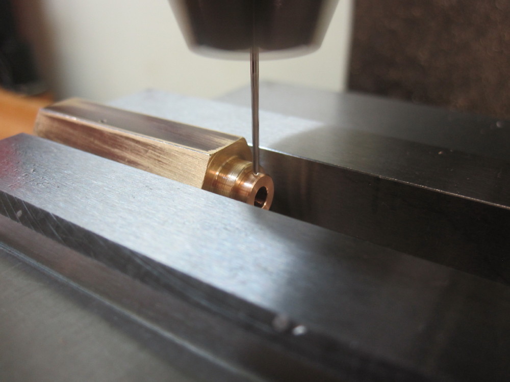
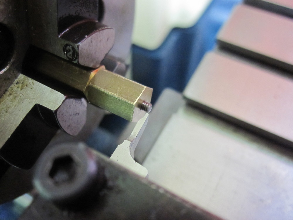
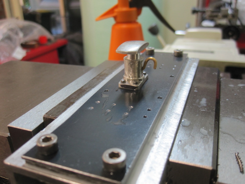
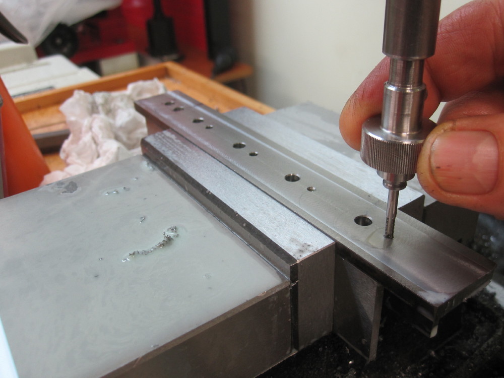
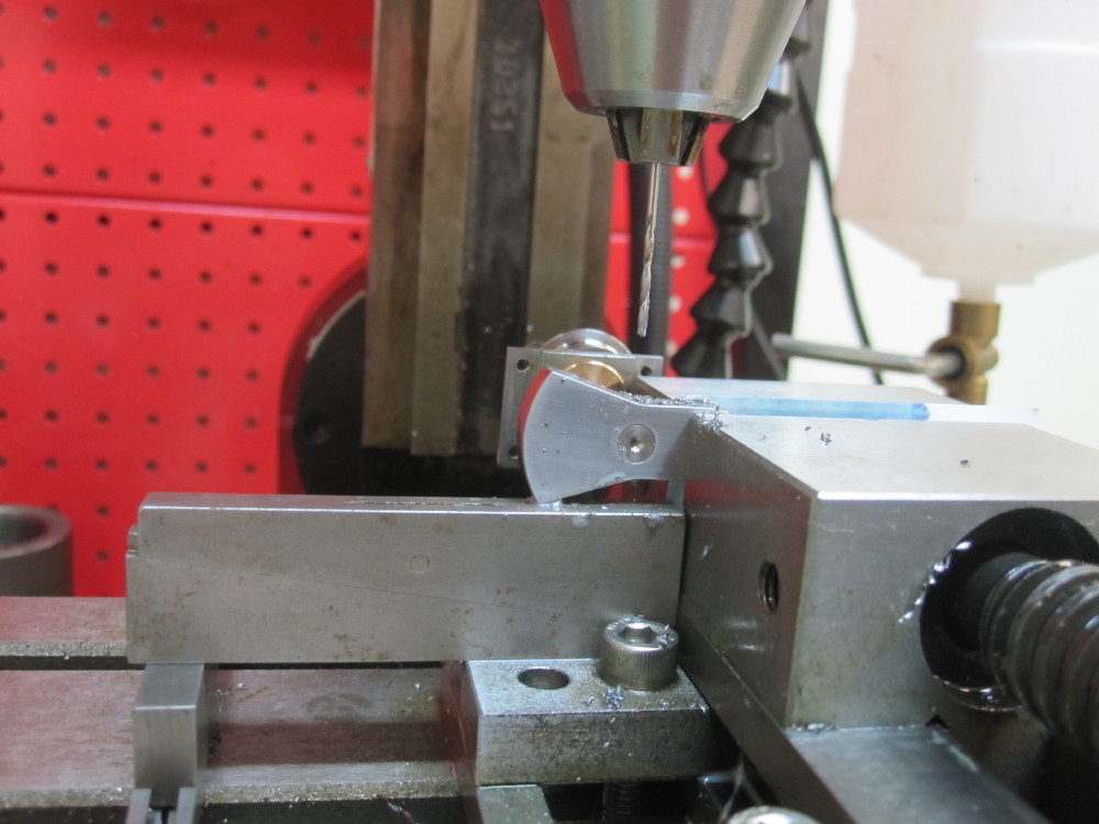
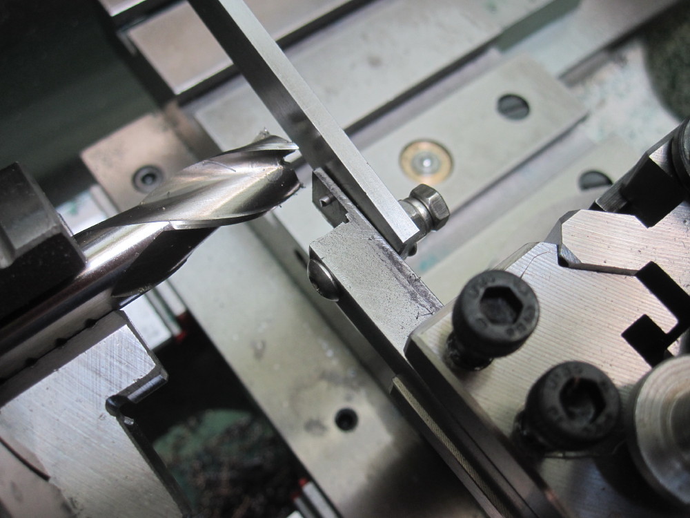
Spot and drilling begins
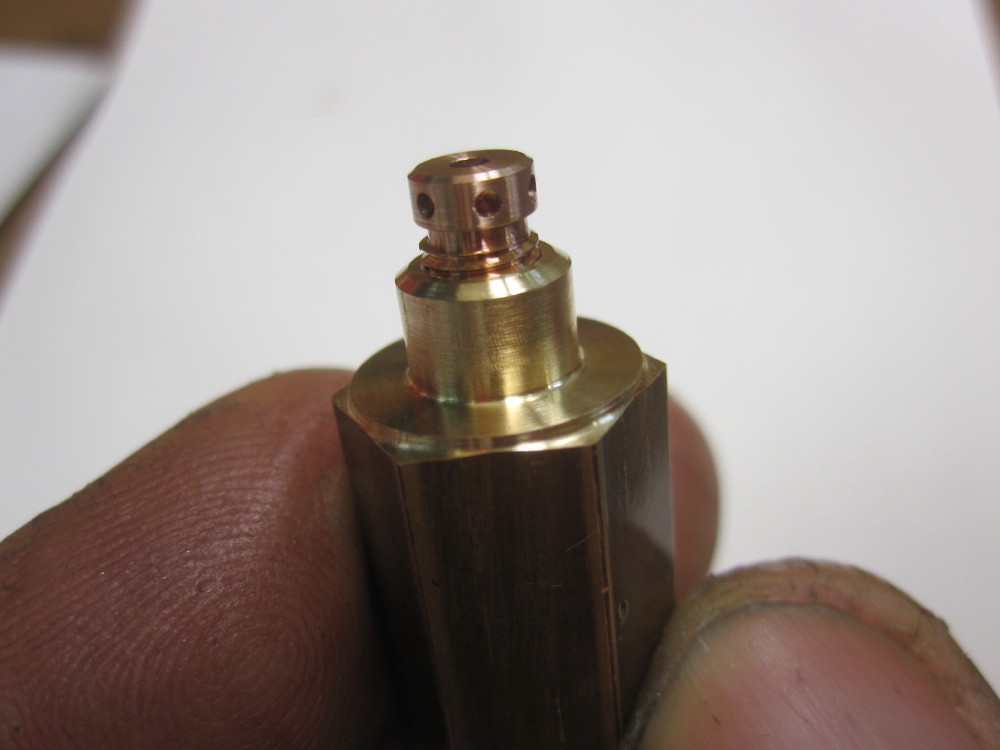
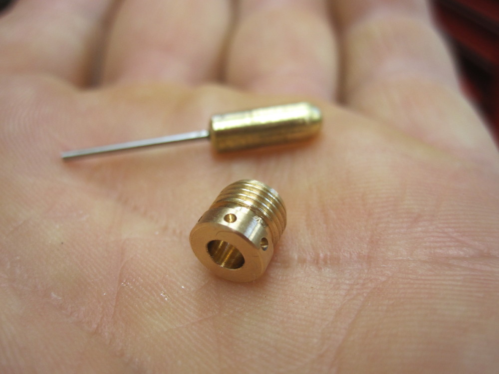
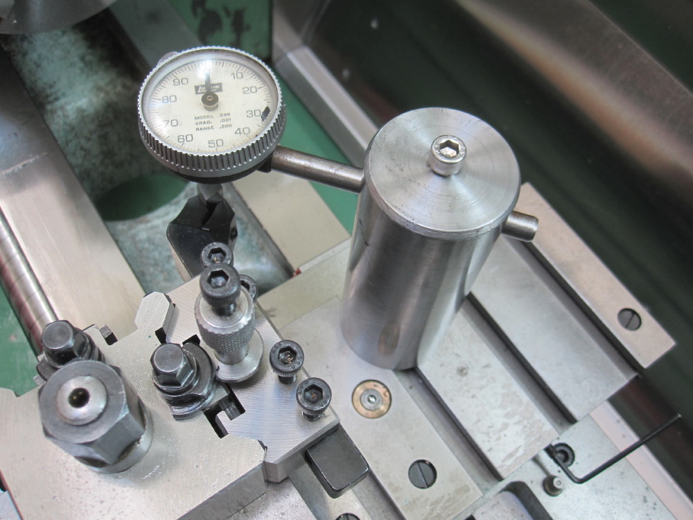
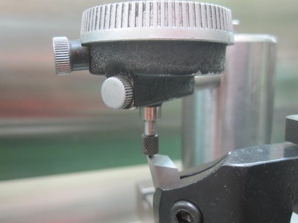
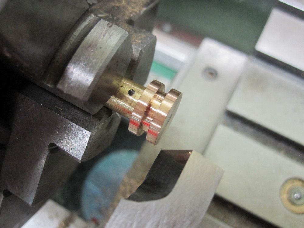
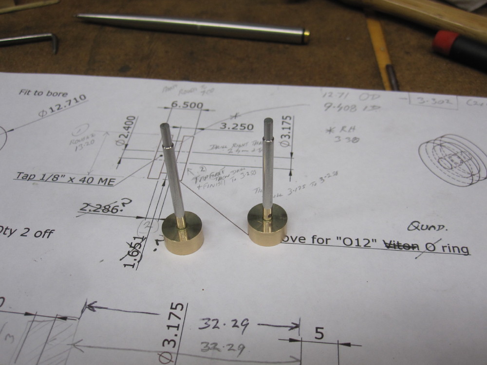
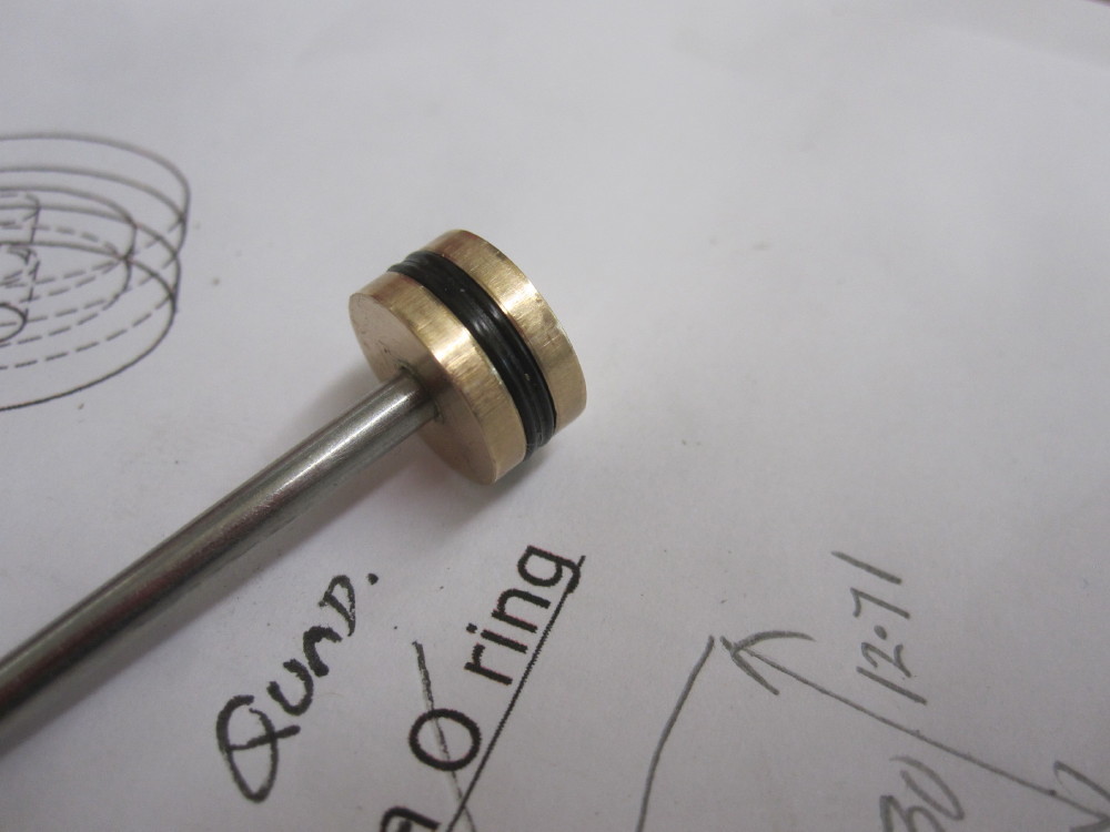
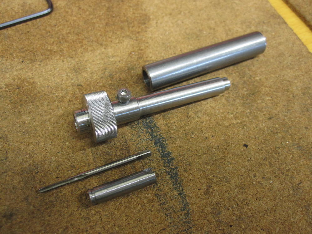
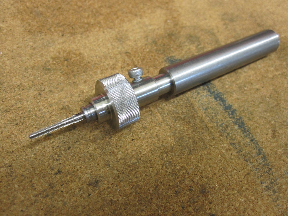
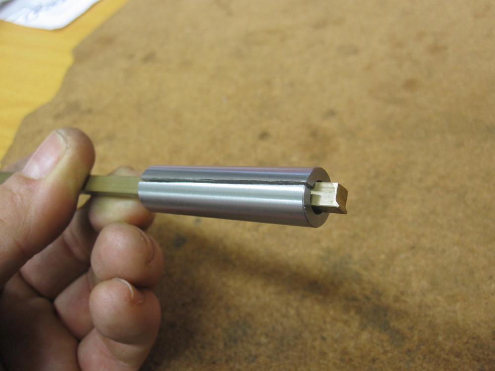
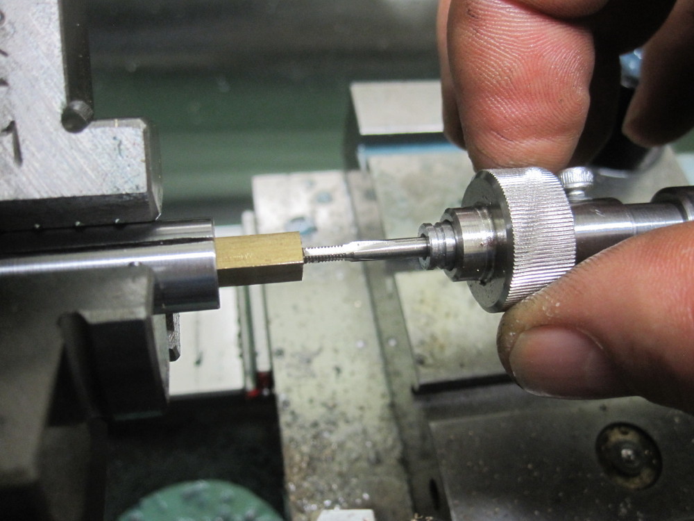
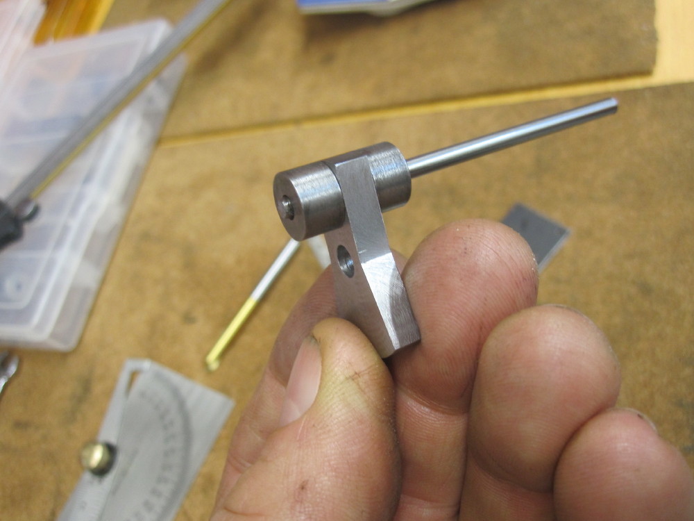
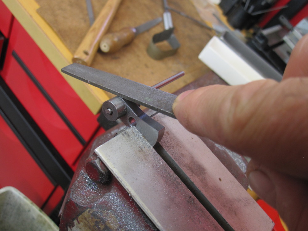
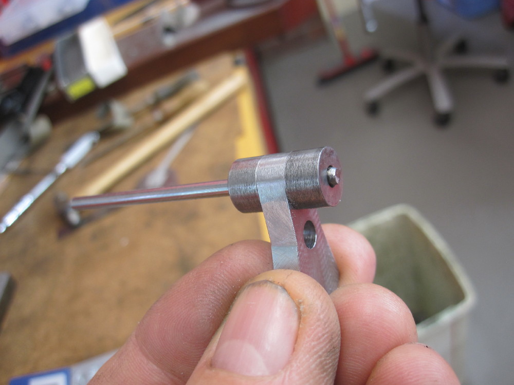
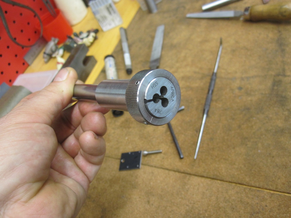
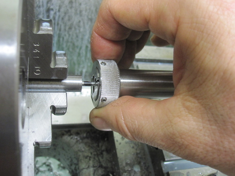
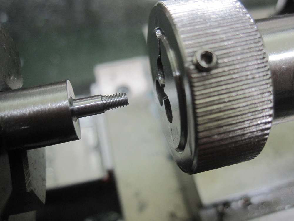
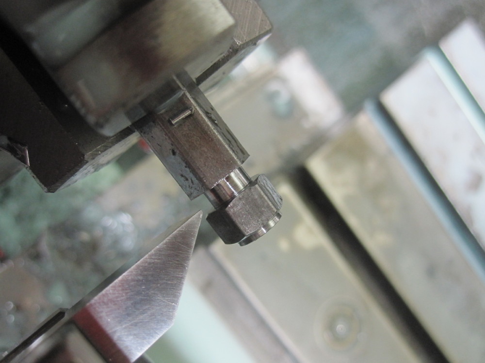
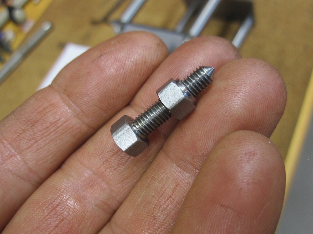
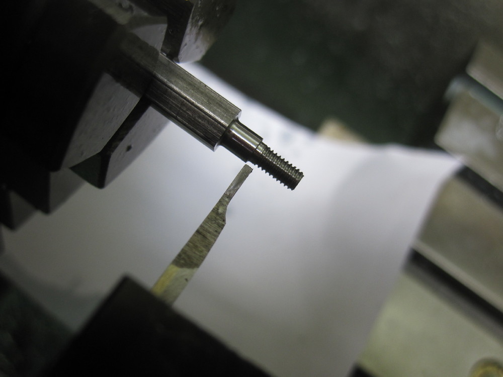
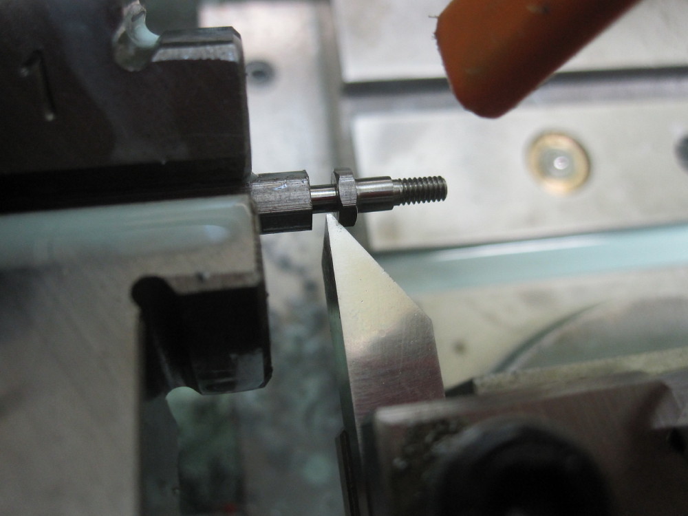
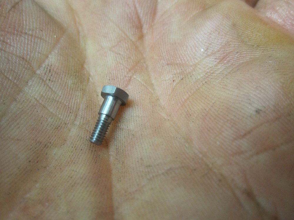
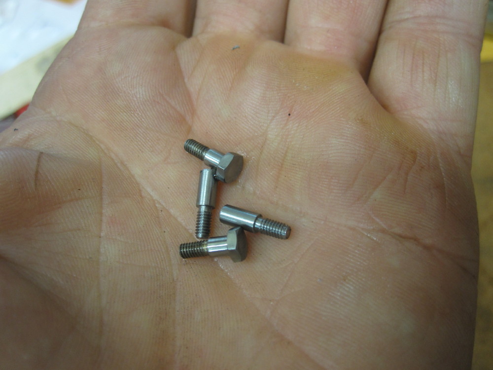
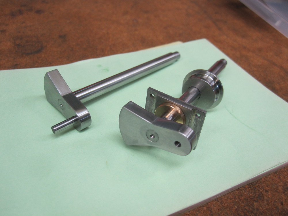
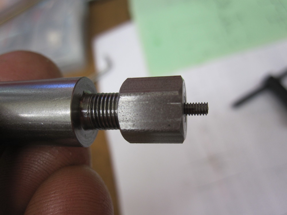
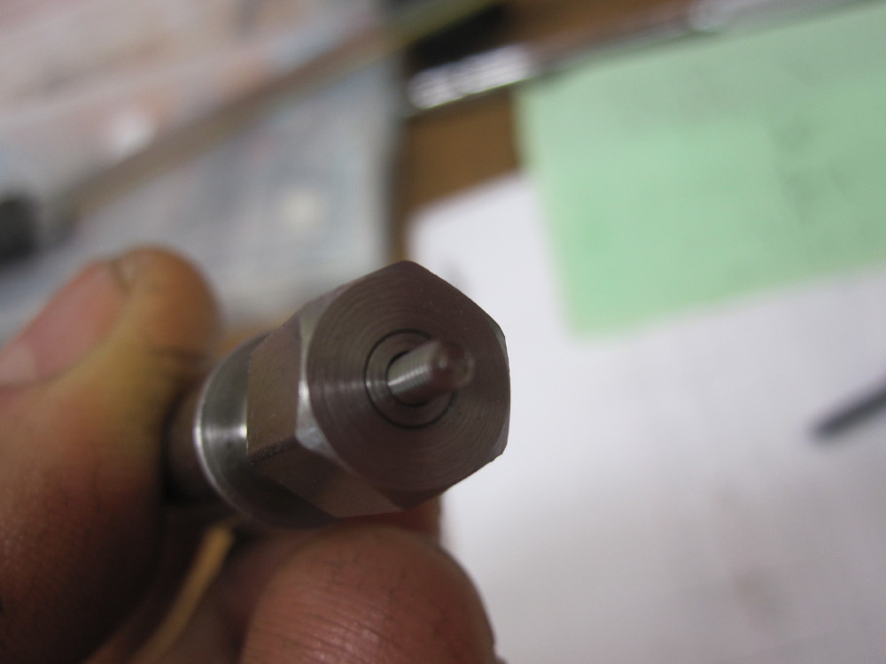
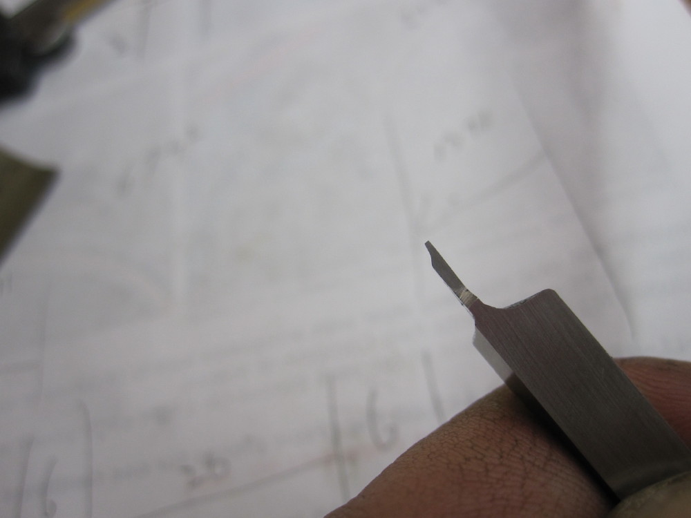
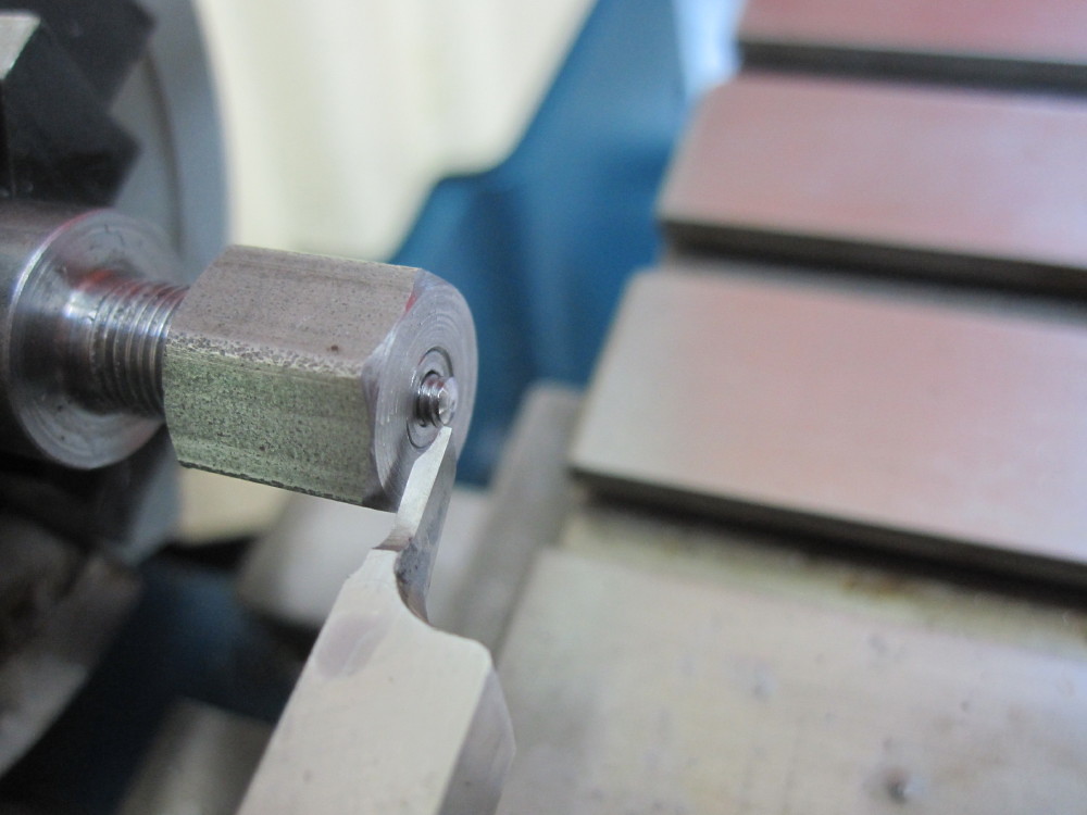
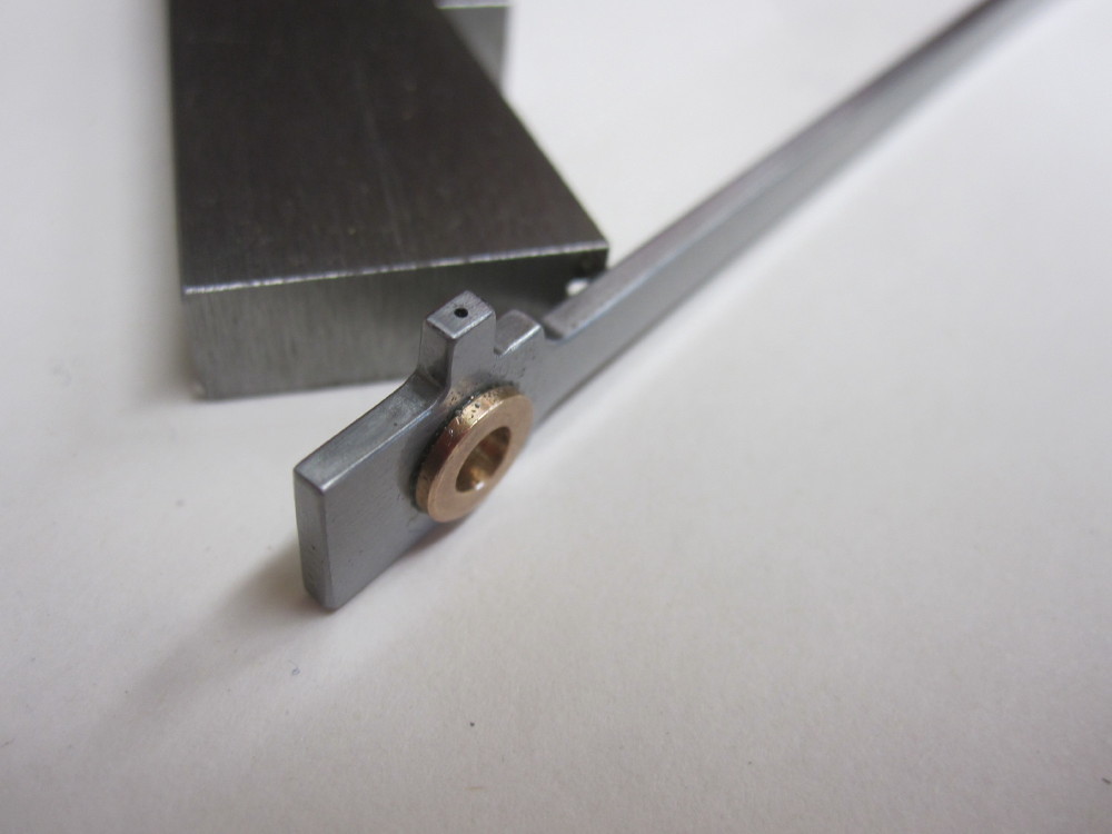
Thread taping using a tool inspired by B.W's book.
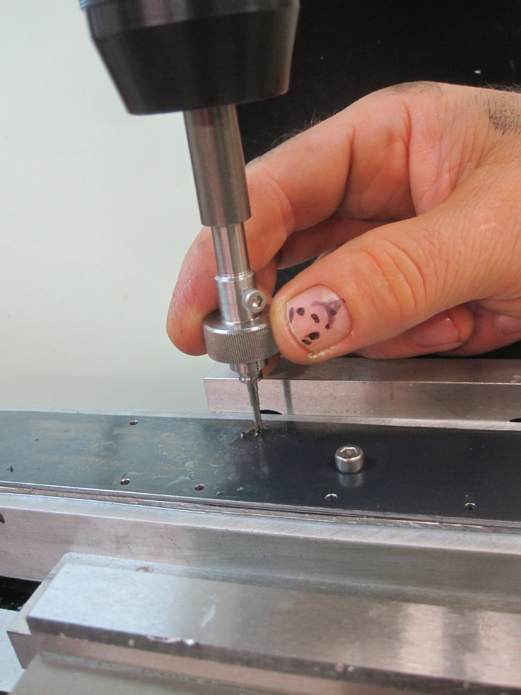
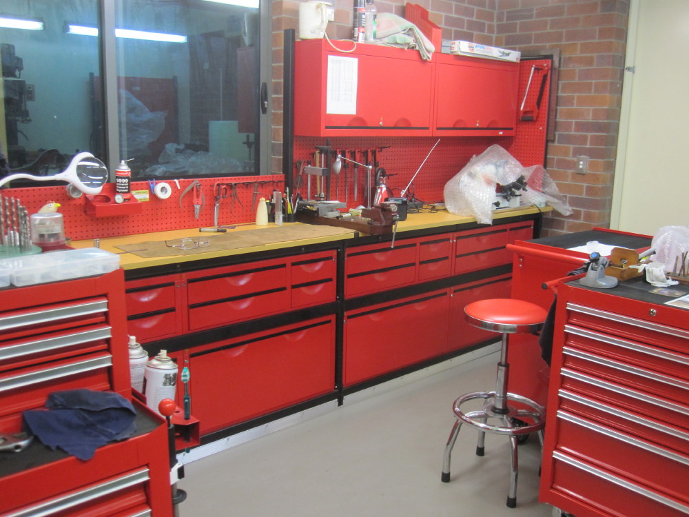
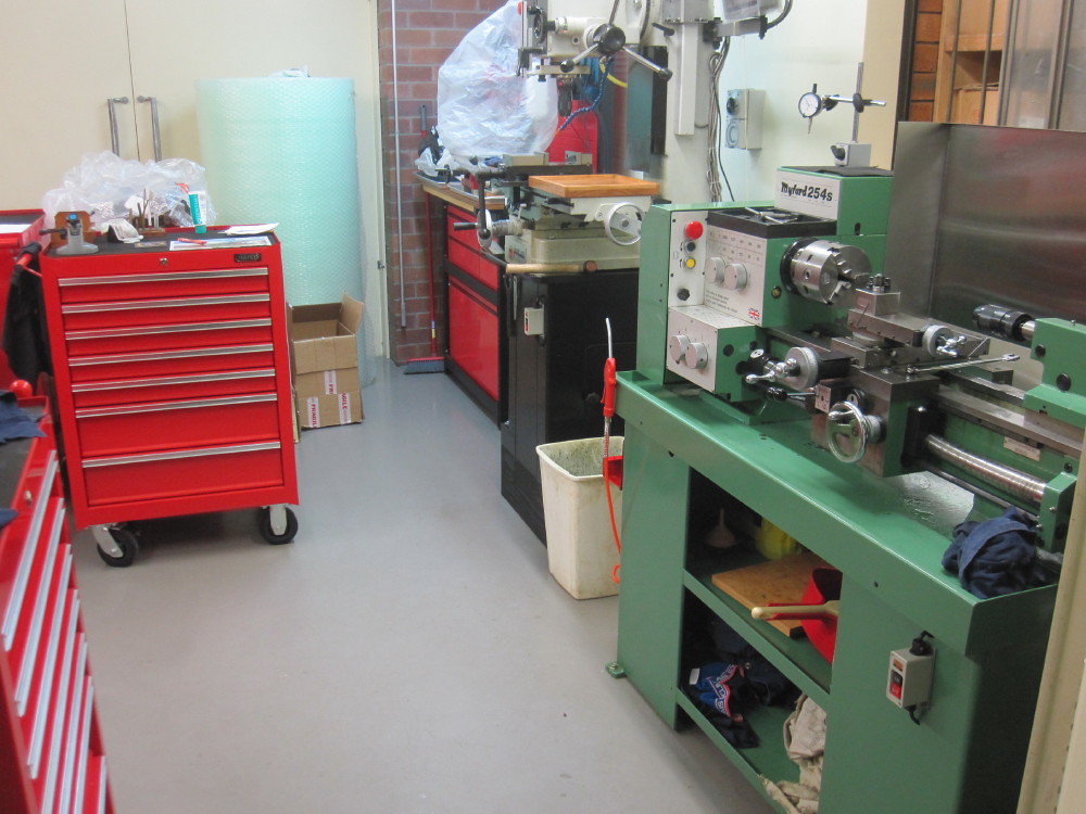
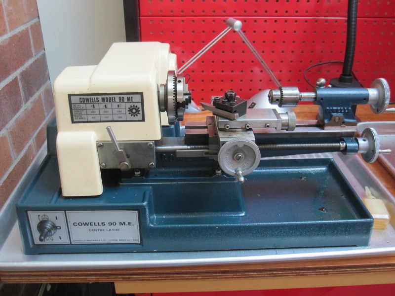
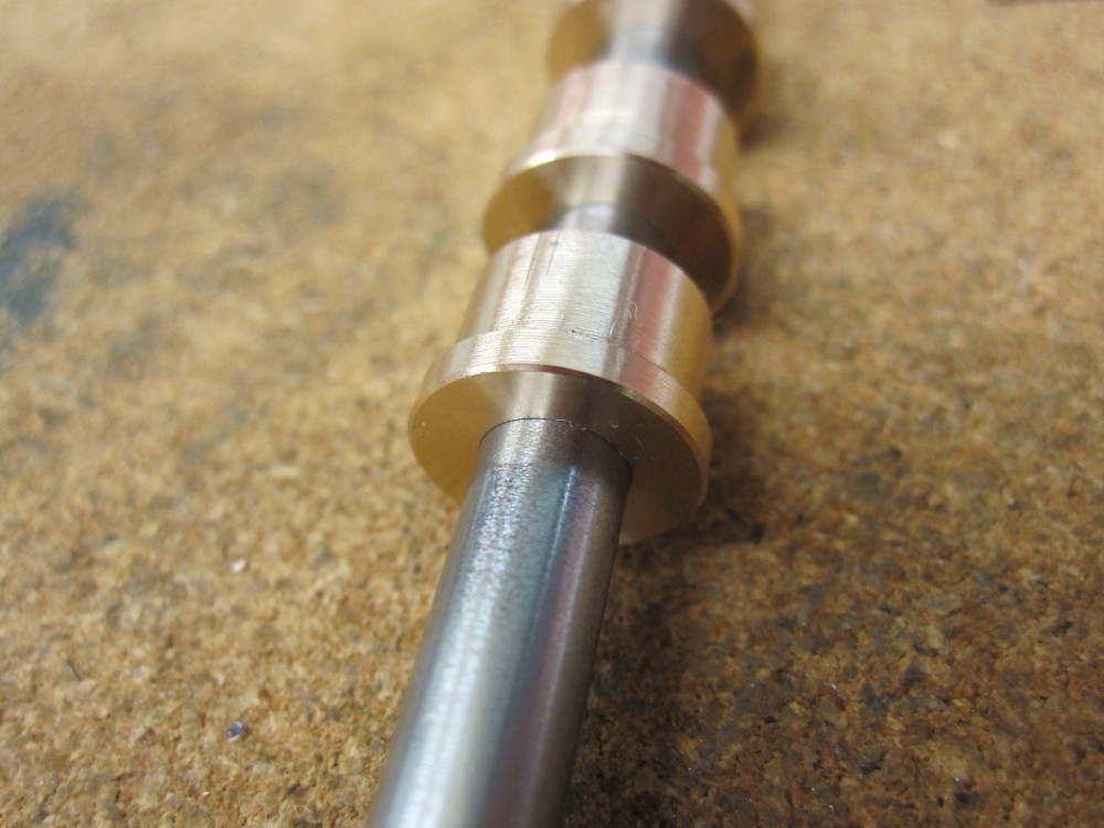
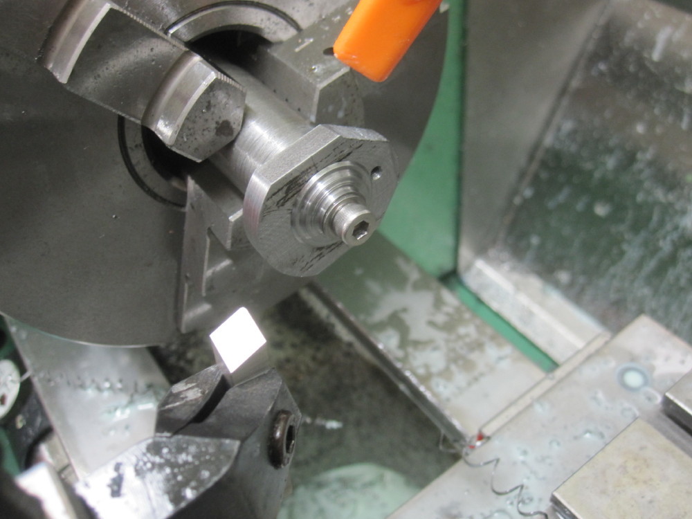
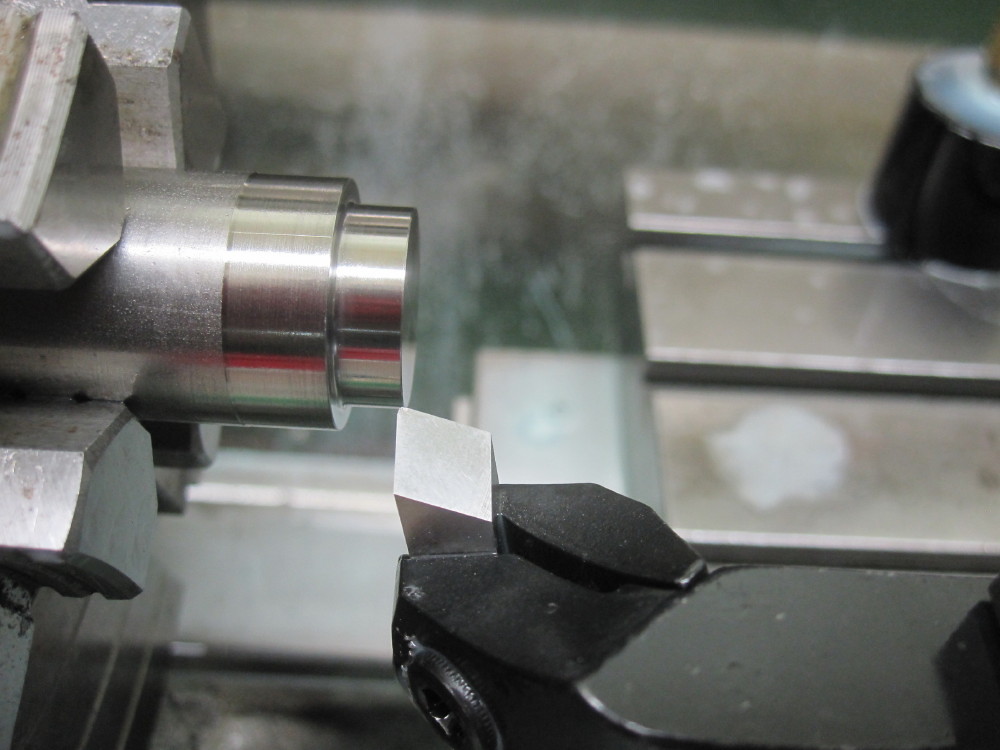
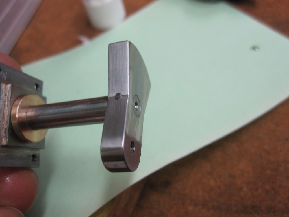
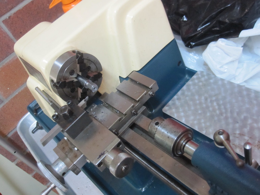
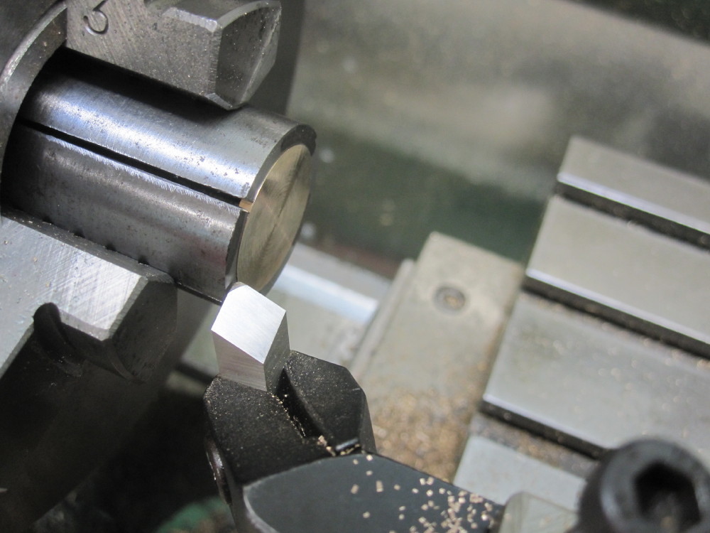
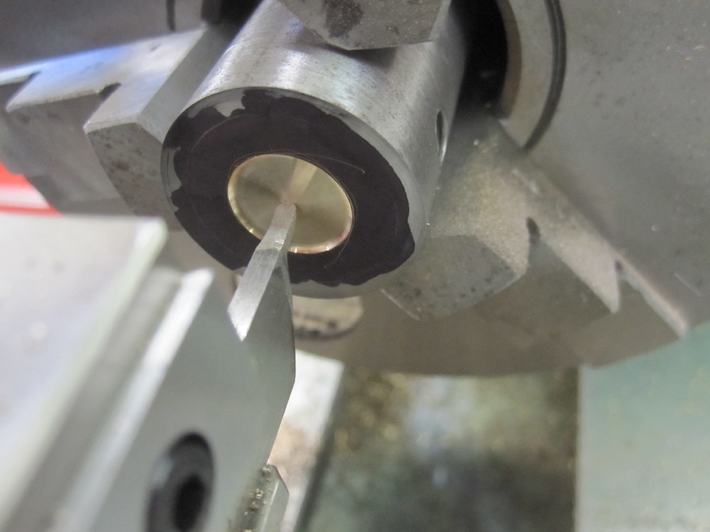
I made this taping tool body from stainless steel that I had to hand, roughed out on the Blue lathe in the bike making room and then the final machining in the Red Room Myford. BW says make it 1/8" for the shanks but I find the tap shank sizes all vary and are all over the place so I make interchangeable sleeves from 1/4" steel to ensure a snug fit for the different size shanks. It all works a total treat. Very pleased and worth the effort and a tool I will end my earthly days using.
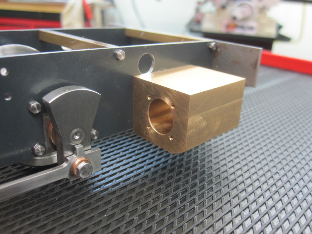
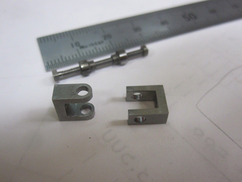
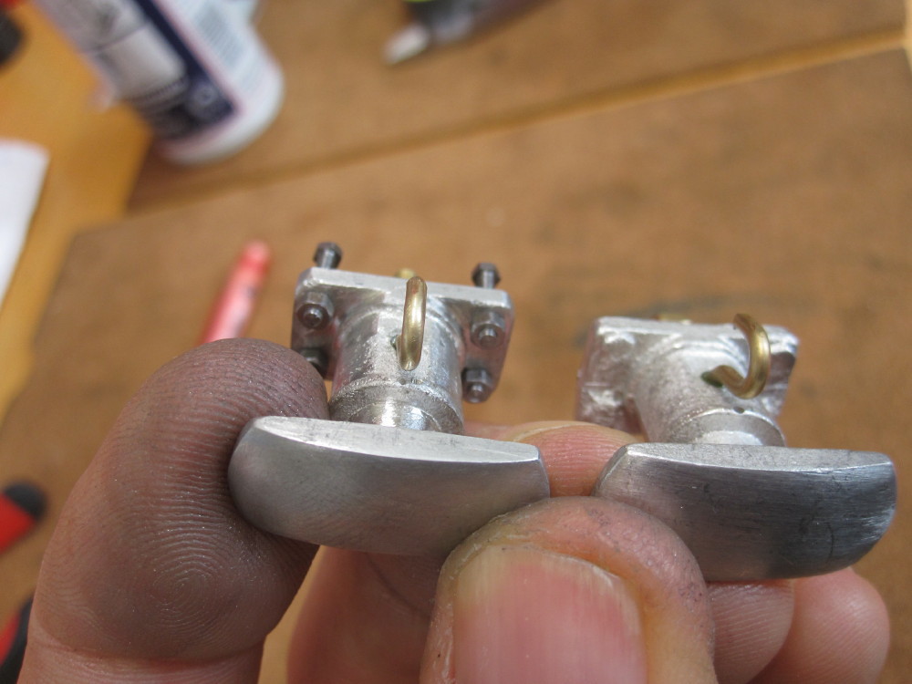
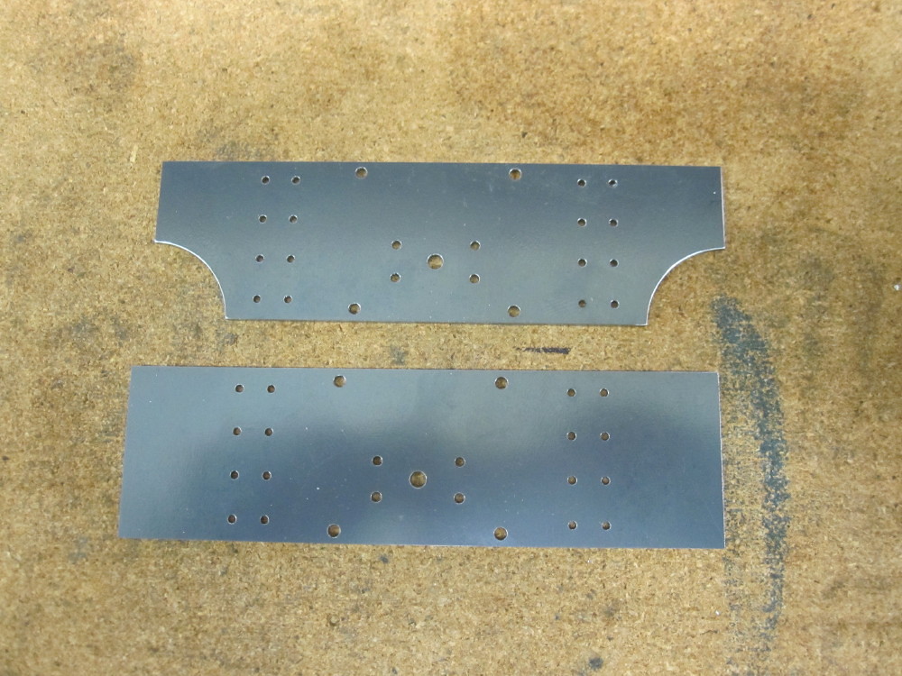
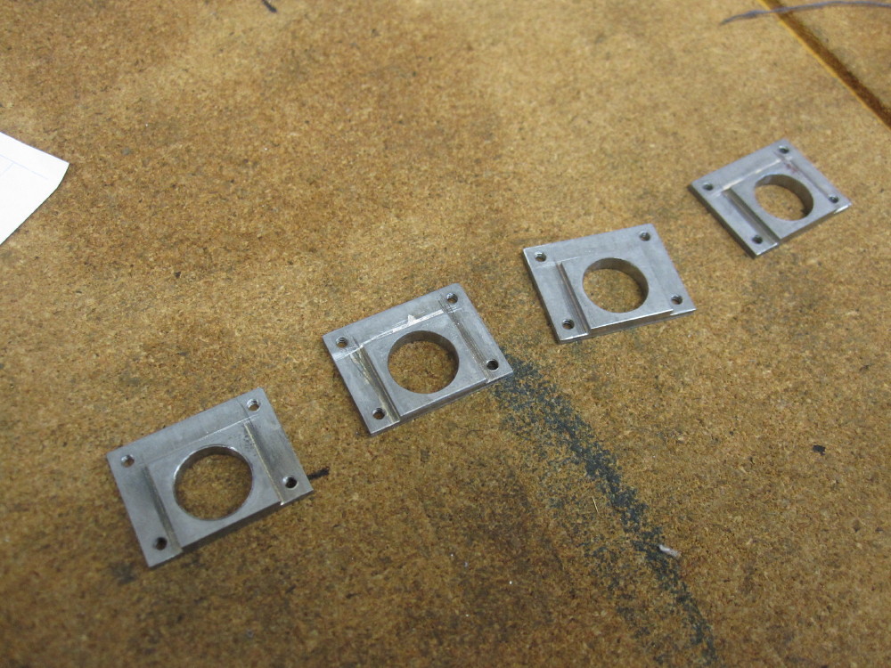
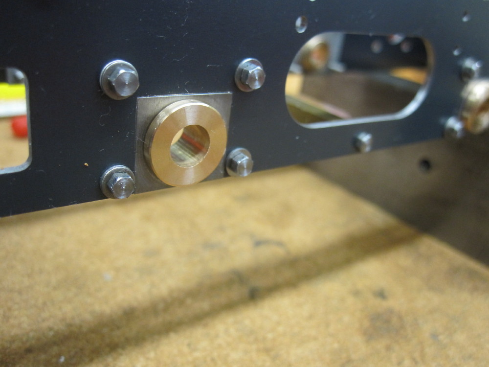
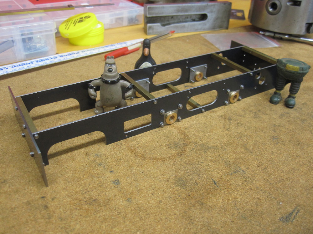
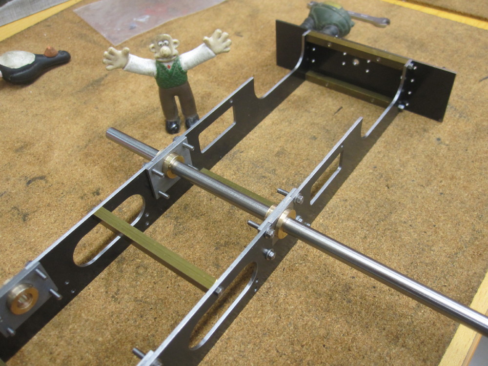
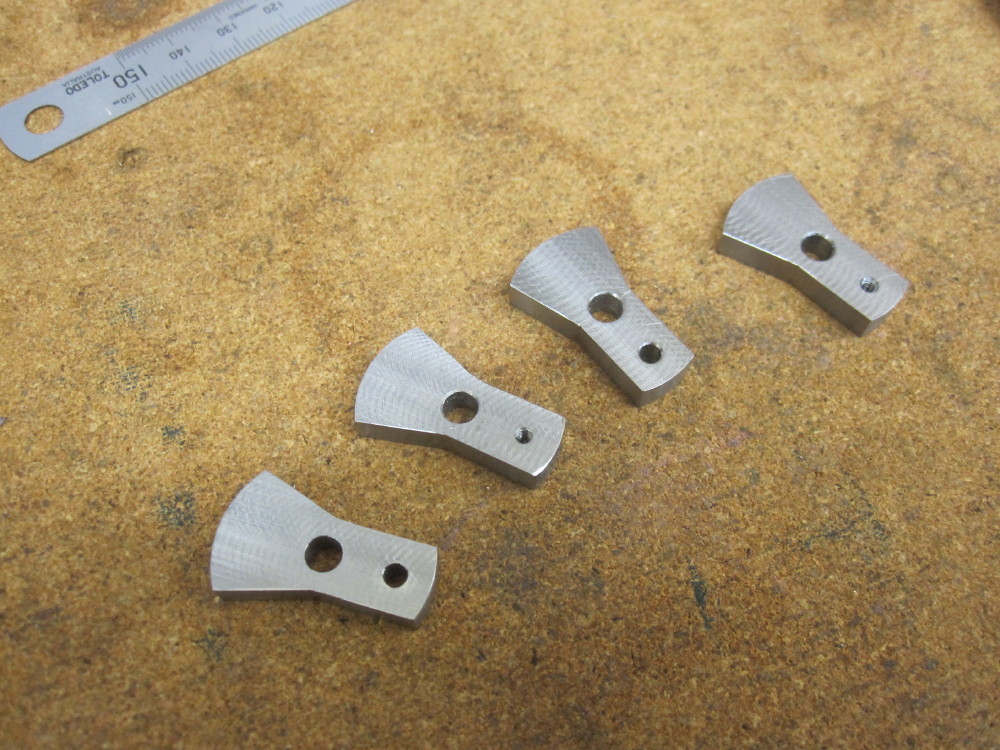
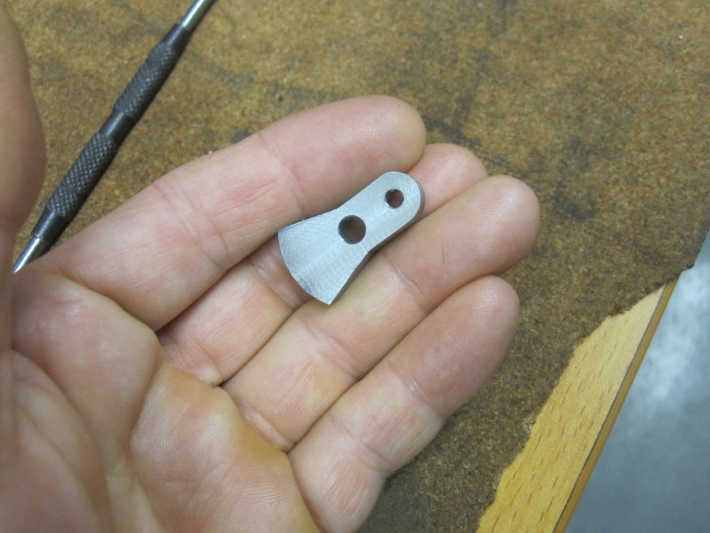
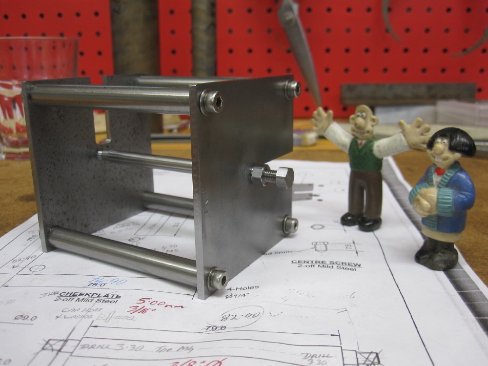
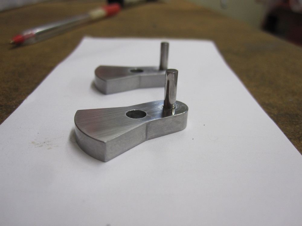
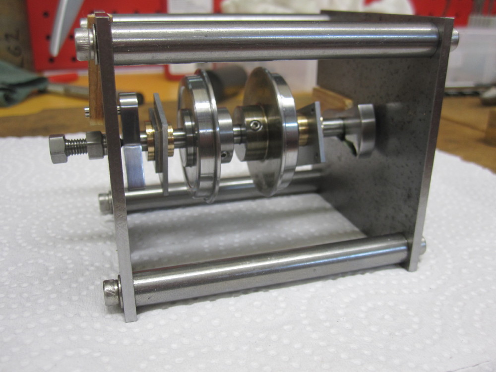
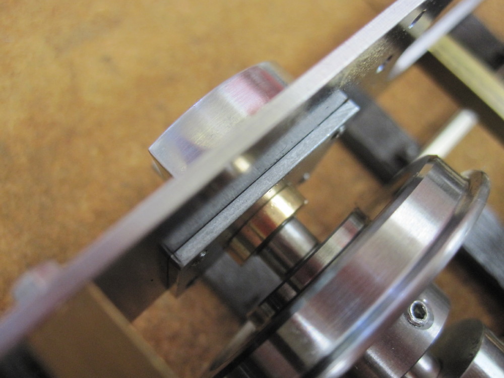
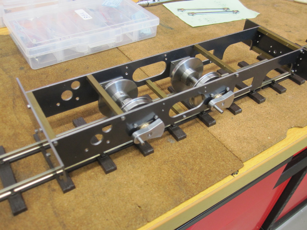
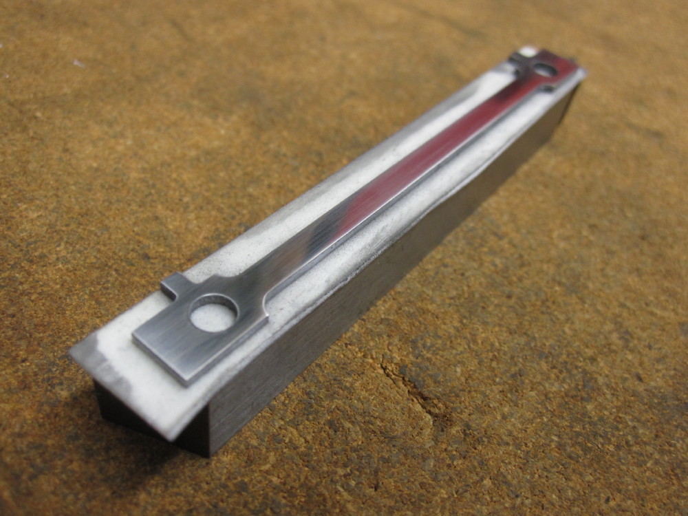
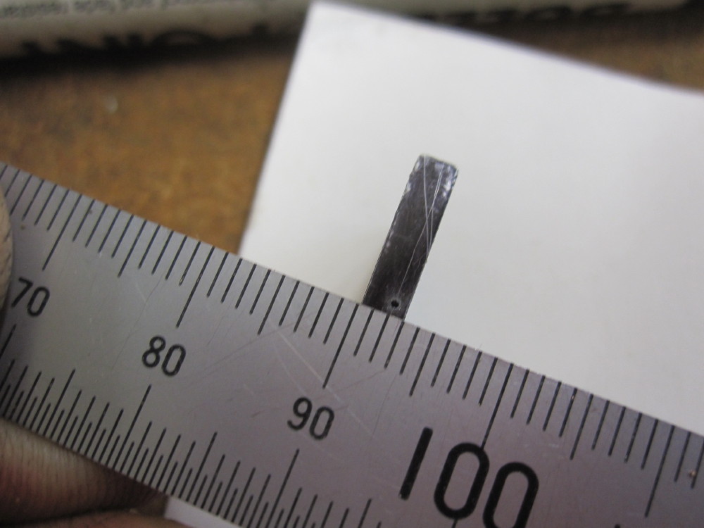
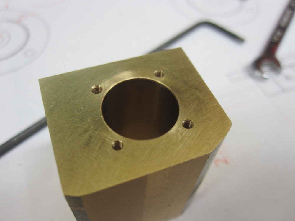
Frame plates completed.
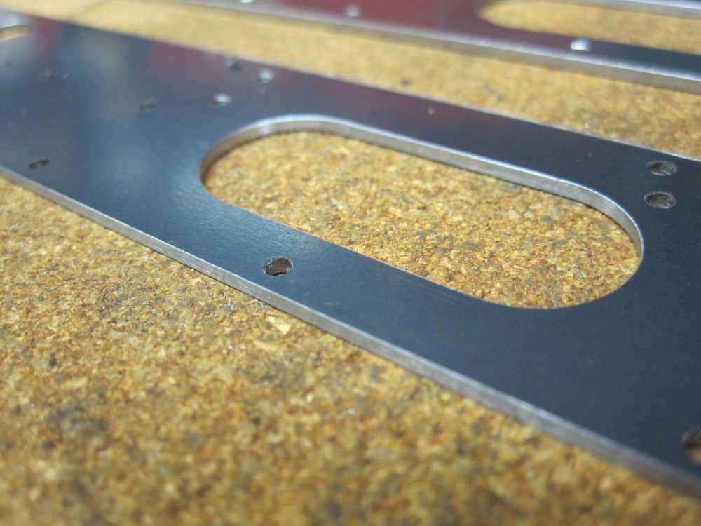
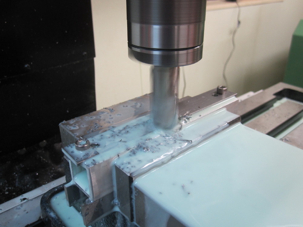
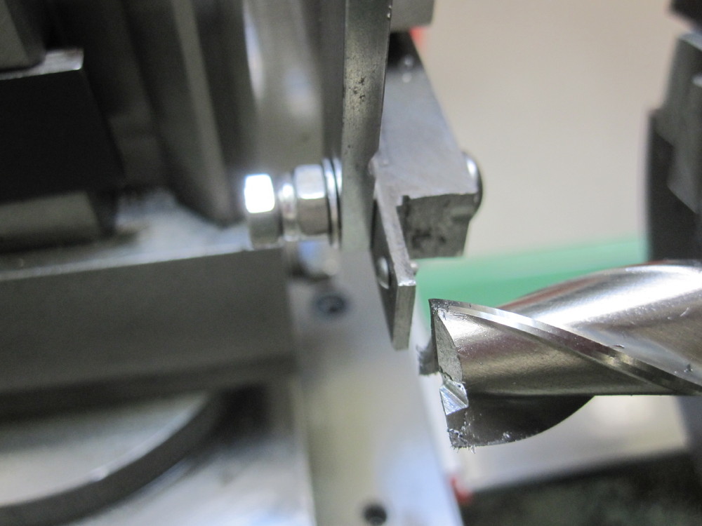
I used a boring head for the first time to do the corners on the cutouts.


 ]
]