I have put together a guide to how I go about making the models that I print in Sketchup.
It is intended to follow on throw the beginners guides in the reference section.
This is the link to download it. https://www.dropbox.com/s/9etz7iqswzqzh ... e.pdf?dl=0
If you are interested in this topic have a look at it. Let me know if you find it helpful or not. If it is helpful I can take it further. Perhaps how I made the gearbox for 4415, how I draw wheels with tapered flanges, how I made a wagon turntable, how I made the spectacle plate for 4415. However it represents significant effort to do it - and I will only do so if I am asked to do it!
Trevor
3 D Printing 16mm models
-
Trevor Thompson
- Trainee Driver

- Posts: 978
- Joined: Fri Oct 05, 2018 6:30 pm
- Location: South West Wales
-
Trevor Thompson
- Trainee Driver
- Posts: 978
- Joined: Fri Oct 05, 2018 6:30 pm
- Location: South West Wales
Re: 3 D Printing 16mm models
The engine box lid and top has now printed. Here is the result straight out of the printer:
This has worked as well as I had hoped it would. The surface is very smooth - and ready to just paint. However when I print things on their side like this (roofs are normally printed this way around) there is a tendency for the layers of the model to part. It isn't visible in this photo but it started to show as I handled it. The solution is to bruch acetone over both sides of the component. It makes the surface unevenly shiny - but doesn't otherwise effect the surface finish like it would do if you did the same to an Aifix model with solvent glue. the square lumps on the model are the supports that th eprinter uses to support overhangs while it prints them> They just fall off when you rub a finger over them. They are not attached at the side just at top and bottom.
So the same part with the supports removed, and fitted into position on the chassis:
I have yet to work out how I will fix the engine cover to the chassis. Perhaps 2 frames glued inside the engine box and screws holding it down from underneath. I could just glue it on after fitting the batteries. Decisions regarding batteries and radio control have to be taken first:
It is beginning to look like a loco (but it is a pretty ungainly looking thing!)
Have to print the redesigned gearbox next.
Trevor
- IMG_0759.jpg (344.37 KiB) Viewed 4528 times
So the same part with the supports removed, and fitted into position on the chassis:
- IMG_0766.jpg (336.7 KiB) Viewed 4528 times
- IMG_0767.jpg (303.66 KiB) Viewed 4528 times
- IMG_0769.jpg (363.82 KiB) Viewed 4528 times
Trevor
-
Trevor Thompson
- Trainee Driver
- Posts: 978
- Joined: Fri Oct 05, 2018 6:30 pm
- Location: South West Wales
Re: 3 D Printing 16mm models
I thought you might like to see what the engine casing looks like when ti has some paint on it. So a thin coat of Valejo acrylic polyurethane airbrush primer, followed by a single coat of thinned Humbrol matt Eggshell blue which I found in the box of paints:
And showing more of the front:
The coach in the background has had a very thin coat of the same primer. The locomotive seems to have been painted in a light green, and had the makers name on it in large white letters. So there are a few more coats of paint to go yet - and that can wait until the model is nearly complete!
- IMG_0771.jpg (340.83 KiB) Viewed 4510 times
- IMG_0772.jpg (325.04 KiB) Viewed 4510 times
-
Trevor Thompson
- Trainee Driver
- Posts: 978
- Joined: Fri Oct 05, 2018 6:30 pm
- Location: South West Wales
Re: 3 D Printing 16mm models
Now for something slightly different.
I placed this thread under the general heading because I want to focus on how 3 D printing can affect all parts of garden railways, rather than on a particular model. As some of you will be aware I have been extending my railway during lockdown, and the extension features a station area modelled (loosely?) on the track layout at Tan y Bwlch (That Festiniog Railway again) during the 1860's. ( Perhaps more of that in another thread later). That layout features 3 wagon turntables - which seem to have been prominent features of all British railways until comparatively recently.
So I have printed three wagon turntables. Firstly one I made earlier which has been in situ for a couple of months:
It seems to have acquired some cement dust during ballast laying - and Im waiting for the rain to stop so I can clear the trimmings off the track!
The turntable consists of three components:
The top deck which has the grooves for the wheels in it:
The bottom part of the top deck which has a rectangular block sticking up 0.5mm. This engages with slots in the lower deck to make it locate in four places to align the tracks. The top deck is in two parts so that the best quality surface is available for locating things accurately. This is the lower part of the top deck upside down:
Finally the lower deck which has the slots in it:
Now back to assembling the gearbox for 4415.
Trevor
I placed this thread under the general heading because I want to focus on how 3 D printing can affect all parts of garden railways, rather than on a particular model. As some of you will be aware I have been extending my railway during lockdown, and the extension features a station area modelled (loosely?) on the track layout at Tan y Bwlch (That Festiniog Railway again) during the 1860's. ( Perhaps more of that in another thread later). That layout features 3 wagon turntables - which seem to have been prominent features of all British railways until comparatively recently.
So I have printed three wagon turntables. Firstly one I made earlier which has been in situ for a couple of months:
- IMG_0757.jpg (353.21 KiB) Viewed 4478 times
The turntable consists of three components:
The top deck which has the grooves for the wheels in it:
- IMG_0774.jpg (294.59 KiB) Viewed 4478 times
- IMG_0776.jpg (303.28 KiB) Viewed 4478 times
- IMG_0775.jpg (305.95 KiB) Viewed 4478 times
Trevor
-
Trevor Thompson
- Trainee Driver
- Posts: 978
- Joined: Fri Oct 05, 2018 6:30 pm
- Location: South West Wales
Re: 3 D Printing 16mm models
The gearbox.
It consists of three parts as shown in this view:
They were printed with the side which is on the right of each component flat on th ebed. Printing small parts like this at 5 degrees higher than default makes the face nearest the bed solid and clean. It does make it harder to separate from the raft. The holes for the shafts were opened up with a 3mm drill and then reamed 3mm. Sounds wrong but the plastic cuts undersize. To assemble 3mm shafts were temporarily inserted to align the holes and the end cover bonded to the motor housing:
When that was solid the third component was added. It did need a bit of filing on its mating face because it was an interference fit! It was gently held in the vice and bonded into place:
Note that this third part is thicker because it locates the chain wheel and gear. It is also glued on so as the whole assembly just fits between the frames. That means it can be glued in with my usual acetone. The gears have now been assembled onto their shafts:
The red gears and sprocket are an interference fit on the 3mm shaft, and the grey one a free fit. That meant that the upper shaft was just pressed into the tight hole. However the lower shaft required its holes drilling out to 3.2mm. I said it cuts undersize! The motor has been fitted and lightly bonded into place:
Finally the assembly was fitted into the frames on 4415. It needed the chain shortening by 2 links, but that means there is less slack in the chain:
Trevor
It consists of three parts as shown in this view:
- IMG_0777.jpg (347.47 KiB) Viewed 4452 times
- IMG_0778.jpg (296.18 KiB) Viewed 4452 times
- IMG_0779.jpg (351.2 KiB) Viewed 4452 times
- IMG_0782.jpg (338.39 KiB) Viewed 4452 times
- IMG_0783.jpg (356.35 KiB) Viewed 4452 times
- IMG_0784.jpg (294.09 KiB) Viewed 4452 times
-
-steves-
- Administrator

- Posts: 2444
- Joined: Thu Jul 28, 2011 1:50 pm
- Location: Cambridge & Peterborough
Re: 3 D Printing 16mm models
Looking absolutely fantastic, some awesome CAD work too 
The buck stops here .......
Ditton Meadow Light Railway (DMLR)
Member of Peterborough and District Association
http://peterborough.16mm.org.uk/
Ditton Meadow Light Railway (DMLR)
Member of Peterborough and District Association
http://peterborough.16mm.org.uk/
-
Trevor Thompson
- Trainee Driver
- Posts: 978
- Joined: Fri Oct 05, 2018 6:30 pm
- Location: South West Wales
Re: 3 D Printing 16mm models
So another digression from 4415:
I have already mentioned that I am making a live steam model of "Linda" - with a tender as running on the Festiniog railway. I have produced a set of inserts to go inside the tender to separate and hold the different parts in place.
So firstly the lower tray. It is intended to provide an insulating platform to electrically isolate the circuitry from the metalwork. It has an indentation to hold the receiver batteries. The smaller slot is for the gas pipe, and the longer slot for the servo leads:
The green box is a mock up of 4 AAA batteries in a square (2 x 2) holder. The second layer has a a cover to hold the batteries down, and a space for the water level indicator circuit and a cover over the receiver (Deleting RX102 (or should that be 104)) Anyway it is mocked up in red:
The third level is a support to hold a charging socket and a slide switch. The switch is held down by 2 10BA bolts. The holes for them are printed in, and then drilled 1.4mm and tapped:
And finally the cover to hide it all. I have yet to redraw this because as it is it has loads of faults. I have messed about with the basic shapes too much. What I am trying to do is make a cover which will hide the electronics yet allow me so see the LEDs. I want it to slope and when covered in real coal look realistic. It has to have some form of hump in it to make room over the gas filler:
And 2 views of it all in place. The circuit board with the LEDs on it has been gently filed to make it a light press fit into its slot It has all been glued down using Gorilla glue:
Trevor
I have already mentioned that I am making a live steam model of "Linda" - with a tender as running on the Festiniog railway. I have produced a set of inserts to go inside the tender to separate and hold the different parts in place.
So firstly the lower tray. It is intended to provide an insulating platform to electrically isolate the circuitry from the metalwork. It has an indentation to hold the receiver batteries. The smaller slot is for the gas pipe, and the longer slot for the servo leads:
- Screen Shot 2020-08-27 at 09.39.20.png (407.49 KiB) Viewed 4340 times
- Screen Shot 2020-08-27 at 09.40.56.png (422.67 KiB) Viewed 4340 times
- Screen Shot 2020-08-27 at 09.41.34.png (427.11 KiB) Viewed 4340 times
- Screen Shot 2020-08-27 at 09.41.45.png (421.35 KiB) Viewed 4340 times
- IMG_0780.jpg (361.42 KiB) Viewed 4340 times
- IMG_0781.jpg (371.71 KiB) Viewed 4340 times
-
Trevor Thompson
- Trainee Driver
- Posts: 978
- Joined: Fri Oct 05, 2018 6:30 pm
- Location: South West Wales
Re: 3 D Printing 16mm models
I have just had one of this moments when you have to laugh out loud at something which has worked better than you thought possible!
So I have to share it. A key visible feature of this locomotive are the louvred shutters which form the cab side windows. Any model of this loco would have to have them. I have drawn them up as proper louvered windows just as in the prototype. Triangular louvres no less, each the proper spacing from the next. Look at the result:
The louvre on the left is face side up. You can see through the louvres!!! The right hand one is the back face. The marks are where the supports were attached. They won't be easily seen so they can stay as they are. I have drawn the slides onto the cab sides, a little thicker than scale, but pretty accurate. The slot has had a file through it to remove the supports. Here is the result with the window closed:
and with the window slid open:
and a slightly different view:
The rest of the cab is printing out as I write this.
Trevor
So I have to share it. A key visible feature of this locomotive are the louvred shutters which form the cab side windows. Any model of this loco would have to have them. I have drawn them up as proper louvered windows just as in the prototype. Triangular louvres no less, each the proper spacing from the next. Look at the result:
- IMG_0787.jpg (306.97 KiB) Viewed 4333 times
- IMG_0788.jpg (332.02 KiB) Viewed 4333 times
- IMG_0789.jpg (351 KiB) Viewed 4333 times
- IMG_0790.jpg (325.45 KiB) Viewed 4333 times
Trevor
Re: 3 D Printing 16mm models
That's coming along quickly - and you're right, the louvres are pretty exciting...
Re livery, I think it carried "photographic grey" livery during its time on the WHR and FR, which would fit with the idea of it being a demonstration model on trial - I believe that's the livery the team restoring the real thing are going for.
Cheers,
Andrew.
Re livery, I think it carried "photographic grey" livery during its time on the WHR and FR, which would fit with the idea of it being a demonstration model on trial - I believe that's the livery the team restoring the real thing are going for.
Cheers,
Andrew.
-
Trevor Thompson
- Trainee Driver
- Posts: 978
- Joined: Fri Oct 05, 2018 6:30 pm
- Location: South West Wales
Re: 3 D Printing 16mm models
Thanks for the information on the livery. That is really important to me. I like to make things as they were.
Yes it is coming along quickly - the cab is mostly printed.
Trevor
Yes it is coming along quickly - the cab is mostly printed.
Trevor
-
Trevor Thompson
- Trainee Driver
- Posts: 978
- Joined: Fri Oct 05, 2018 6:30 pm
- Location: South West Wales
Re: 3 D Printing 16mm models
The latest components printed and assembled:
I have had issues printing the spectacle plate. Sketchup only identifies "nested object" issues in the inspector subroutine, so it should be OK. The slicing software loads it and it shows all the correct features. However when it slices it it fills the spectacles and the hole for battery access. I ended up chain drilling and filing them out.
I am now printing the cab detail. The radiator, a prominent feature in the cab, is here:
and the reverse face:
The back is a bit rough. The result of having to remove the printing supports and rub a file ofer it. This reverse face will hardly be visible anyway so I am not concerned about that.
- IMG_0791.jpg (383.02 KiB) Viewed 4164 times
- IMG_0793.jpg (354.56 KiB) Viewed 4164 times
I am now printing the cab detail. The radiator, a prominent feature in the cab, is here:
- IMG_0796.jpg (360.29 KiB) Viewed 4164 times
- IMG_0795.jpg (358.73 KiB) Viewed 4164 times
Re: 3 D Printing 16mm models
Never put a grouped or component object through Solid Inspector and expect to get anything meaningful, it always just shows it as a nested object and doesn't look inside the group. You have to 'explode' it first ( and multiple explodes if you've grouped other groups together) and then when you've repaired things to get everything shiny, then you can regroup it.Trevor Thompson wrote: ↑Fri Aug 28, 2020 9:11 am
I have had issues printing the spectacle plate. Sketchup only identifies "nested object" issues in the inspector subroutine, so it should be OK. The slicing software loads it and it shows all the correct features. However when it slices it it fills the spectacles and the hole for battery access.
Philip
-
Trevor Thompson
- Trainee Driver
- Posts: 978
- Joined: Fri Oct 05, 2018 6:30 pm
- Location: South West Wales
Re: 3 D Printing 16mm models
Thanks for the tip.
There were a couple of reversed faces in 2 separate components, and the spectacles needed to have their "faces intersected" Prints OK now.
Trevor
There were a couple of reversed faces in 2 separate components, and the spectacles needed to have their "faces intersected" Prints OK now.
Trevor
Re: 3 D Printing 16mm models
Glad you've got it sorted. It fooled me for quite a while a couple of years ago, before I realised what was happening and it was also part the the problem that Rik was having with his window frames a couple of weeks ago.Trevor Thompson wrote: ↑Fri Aug 28, 2020 10:07 pm
There were a couple of reversed faces in 2 separate components, and the spectacles needed to have their "faces intersected" Prints OK now.
Philip
-
Trevor Thompson
- Trainee Driver
- Posts: 978
- Joined: Fri Oct 05, 2018 6:30 pm
- Location: South West Wales
Re: 3 D Printing 16mm models
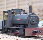
4415 is now finished as in all the parts are printed and assembled. I await the arrival of rechargeable batteries and a radio receiver. So in the meantime it is being painted. Much easier to see the result when it isn't black!
So it has had a primer coat, a "round" coat of duck egg blue matt enamel. After 24 hours I rubbed the surface lightly with a glass fibre pen, and gave it another generous coat of paint - this time matt green. I will rub it down again and then paint it with a final 2 coats of grey.
So the photos:
and finally with the roof in place. The roof is interesting as a printing problem. I have successfully printed it, but there are a couple of cracks in the edges where it is thin. Easily filled and not affecting the structural strength - in that it doesn't want to split down the crack. However not perfect. The filling is visible.
And while thinking about surface finish on my printed models I have a photo of the Ashbury 4 wheel coaches also in the process of being printed. Some surface blemishes are still visible but they will disappear after another couple of coats of paint have been applied:
Trevor
So it has had a primer coat, a "round" coat of duck egg blue matt enamel. After 24 hours I rubbed the surface lightly with a glass fibre pen, and gave it another generous coat of paint - this time matt green. I will rub it down again and then paint it with a final 2 coats of grey.
So the photos:
- IMG_0806.jpg (307.39 KiB) Viewed 4059 times
- IMG_0805.jpg (316.13 KiB) Viewed 4059 times
- IMG_0807.jpg (297.01 KiB) Viewed 4059 times
- IMG_0808.jpg (330.85 KiB) Viewed 4059 times
- IMG_0801.jpg (272.83 KiB) Viewed 4059 times
Re: 3 D Printing 16mm models
Looking Good, Trevor.
I notice that earlier you said you don't need to do any rubbing down before painting. Have you found that ABS gives a better finish than PLA?
Rik
I notice that earlier you said you don't need to do any rubbing down before painting. Have you found that ABS gives a better finish than PLA?
Rik
Re: 3 D Printing 16mm models
My efforts are nowhere up the the quality and standard of Trevor and Philip - maybe because my printer cost only £80 - or maybe because I'm not so skilled at setting up up properly. Prints which are mostly along the X and Y axis are acceptable
.
So these ends and sides of my luggage van have turned out quite well. I've added a bit of detail with plasticard
.
And mounted everything on the ubiquitous HLW chassis
.
Almost finished ...
,
Whereas these ridge tiles which were printed upright and so mostly along the Z axis are heavily ribbed
.
I think it's because the frame of my printer is made from 4mm ply and so, even though I've added extra framework to try and stabilise it, it flexes a bit.. However, once installed, the ridge tiles seem OK
Rik
- IMG_1085.JPG (84.48 KiB) Viewed 4088 times
So these ends and sides of my luggage van have turned out quite well. I've added a bit of detail with plasticard
- IMG_1088.JPG (99.33 KiB) Viewed 4088 times
And mounted everything on the ubiquitous HLW chassis
- IMG_1094.JPG (116.91 KiB) Viewed 4088 times
Almost finished ...
- IMG_1100.JPG (111.34 KiB) Viewed 4088 times
Whereas these ridge tiles which were printed upright and so mostly along the Z axis are heavily ribbed
- IMG_1087.JPG (75.45 KiB) Viewed 4088 times
I think it's because the frame of my printer is made from 4mm ply and so, even though I've added extra framework to try and stabilise it, it flexes a bit.. However, once installed, the ridge tiles seem OK
- IMG_1106.JPG (116.51 KiB) Viewed 4088 times
-
Trevor Thompson
- Trainee Driver
- Posts: 978
- Joined: Fri Oct 05, 2018 6:30 pm
- Location: South West Wales
Re: 3 D Printing 16mm models
Rik
I don't do any rubbing down normally. For example the coach has not been rubbed down at all - and won't need anything more than another coat of paint. I think I printed that on the high resolution setting. However the sides of the 4415 are not as smooth as I have been able to get other components. I suspect that I printed them using the standard resolution. If you look closely at the flat panels of 4415 you will see that they are not actually perfect. I will give them some attention to lower the raised marks.
I much prefer to cover any slight surface irregularities with paint - rather than removing plastic. It is amazing how a few fairly thick layers will improve the surface. I am spraying the paint using an airbrush so it is fairly thin, and I spray until the paint is just about to run. I need good light to do it though. So a few thick coats don't actually build up a very thick paint film
-
Trevor Thompson
- Trainee Driver
- Posts: 978
- Joined: Fri Oct 05, 2018 6:30 pm
- Location: South West Wales
Re: 3 D Printing 16mm models
PS I don't think it makes any difference whether I use PLA or ABS. I only prefer ABS because can be bonded with Acetone - which I had in the garage.
-
Trevor Thompson
- Trainee Driver
- Posts: 978
- Joined: Fri Oct 05, 2018 6:30 pm
- Location: South West Wales
Re: 3 D Printing 16mm models
Rik
I have been thinking about this overnight!
I think that the wagon and the tiles are pretty brilliant considering that you have produced them on such a low cost printer. You would not know how the tiles were made.
I have 2 questions:
Firstly what do you use to glue the wagon components together - they are PLA I think?
Secondly how are you going to finish (paint) the wagon?
Looking forward to photos of the wagon when its painted.
Trevor
Who is online
Users browsing this forum: No registered users and 12 guests