A bit of time in the shed
-
Busted Bricks

- Trainee Driver

- Posts: 750
- Joined: Sat Jan 22, 2011 9:16 pm
- Location: Denmark
- Contact:
Re: A bit of time in the shed
Those chassis are really nice. If you get fed up cutting out frames and connecting rods by hand let me know. They wouldn't cost a lot to laser cut.
-
-steves-
- Administrator

- Posts: 2421
- Joined: Thu Jul 28, 2011 1:50 pm
- Location: Cambridge & Peterborough
Re: A bit of time in the shed
Thanks, appreciate that, we will see how it goesBusted Bricks wrote: ↑Tue Jul 16, 2019 8:12 pm Those chassis are really nice. If you get fed up cutting out frames and connecting rods by hand let me know. They wouldn't cost a lot to laser cut.
The buck stops here .......
Ditton Meadow Light Railway (DMLR)
Member of Peterborough and District Association
http://peterborough.16mm.org.uk/
Ditton Meadow Light Railway (DMLR)
Member of Peterborough and District Association
http://peterborough.16mm.org.uk/
Re: A bit of time in the shed
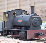
Something for this Steve.
Cranks wouldn't be needed really, just the ability to move like front and rear bogies. Yes the ones I have seen are all with the motor pointing up. I want to replace the one in my Railcar with a power bogie. I would be using the motor as is, so it's a question of if it can be done....
- DSCN4059.JPG (415.42 KiB) Viewed 6666 times
Cranks wouldn't be needed really, just the ability to move like front and rear bogies. Yes the ones I have seen are all with the motor pointing up. I want to replace the one in my Railcar with a power bogie. I would be using the motor as is, so it's a question of if it can be done....
ROD
Life is so easy when I run my trains.


https://gardenrails.org/forum/viewtopic ... 41&t=11364
https://www.youtube.com/@fairywoodlightrailway
Life is so easy when I run my trains.


https://gardenrails.org/forum/viewtopic ... 41&t=11364
https://www.youtube.com/@fairywoodlightrailway
-
-steves-
- Administrator
- Posts: 2421
- Joined: Thu Jul 28, 2011 1:50 pm
- Location: Cambridge & Peterborough
Re: A bit of time in the shed
I would think anything is possible, but for something that specific I would need the entire railcar at hand to measure and see what would fit. A shame you are not closer or you could have popped over and we could have seen if we could have made something to fit.FWLR wrote: ↑Wed Jul 17, 2019 8:04 am Something for this Steve.
DSCN4059.JPG
Cranks wouldn't be needed really, just the ability to move like front and rear bogies. Yes the ones I have seen are all with the motor pointing up. I want to replace the one in my Railcar with a power bogie. I would be using the motor as is, so it's a question of if it can be done....
What is wrong with the one that's in it?
The buck stops here .......
Ditton Meadow Light Railway (DMLR)
Member of Peterborough and District Association
http://peterborough.16mm.org.uk/
Ditton Meadow Light Railway (DMLR)
Member of Peterborough and District Association
http://peterborough.16mm.org.uk/
-
-steves-
- Administrator
- Posts: 2421
- Joined: Thu Jul 28, 2011 1:50 pm
- Location: Cambridge & Peterborough
Re: A bit of time in the shed
Well my attempt is now finished and seems to work well too. Once set up once for zero it's very quick and easy to pop a new crank on and drill it, it will save me sooooo much time going forwardsGTB wrote: ↑Mon Jul 15, 2019 4:03 am Thanks for that. Your description kicked my mind out of a rut. For some reason I had got it fixed in my head when machining cranks to drill the axle hole, then drill and tap for the crankpin and finally drill and tap for the grub screw. Sigh.........
By using the sequence of axle, then grub screw and finally the crankpin, only a simple drilling fixture is needed. I'm waiting on some bits again, so I knocked one up yesterday afternoon.
The photo shows the fixture that I made earlier for machining the quartering flats on the left and the fixture to hold the crank while drilling and tapping for the crankpin on the right. I use a standard size axle for locos, so I only need one set of fixtures for outside cranks.
Outside Crank Jigs.jpg
The only reason they are machined all over is that the only suitable size piece of square bar under the bench was hot rolled steel and far from square, so the surfaces needed cleaning up. I used a fly cutter instead of a milling cutter, as the mill scale on hot rolled steel is as abrasive as the skin on an iron casting and fly cutters are a lot easier to sharpen than a milling cutter.
The axle retaining screw in the quartering fixture is positioned diagonally to use it as a marker, so if it is always facing forward in the vice the quartering flats will be at 90deg when the fixture is changed end for end.
It's a bit hard to see, but there is a flat milled on the 'axle' end sticking out of the crank drilling fixture, effectively it is just a stub axle sticking out of half a quartering jig, but is machined in one piece to maintain alignment.
With a DRO on the mill and a self-centering 4 jaw chuck in the lathe, making these fixtures was quick and easy. I'm not a great fan of jigs/fixtures, so the simpler the better.
Regards,
Graeme


Last edited by -steves- on Thu Apr 09, 2020 6:54 pm, edited 1 time in total.
The buck stops here .......
Ditton Meadow Light Railway (DMLR)
Member of Peterborough and District Association
http://peterborough.16mm.org.uk/
Ditton Meadow Light Railway (DMLR)
Member of Peterborough and District Association
http://peterborough.16mm.org.uk/
Re: A bit of time in the shed
My initial idea was similar to that, except it would have located the crank from the crankpin hole, so I could drill the hole for the grub screw. Then I had a better idea.....
Saving time on batches of parts is what jigs are about. I even went to the trouble of making a spindle stop for the lathe, to reduce setup time for turning rolling stock axles.
The finish on the jigs is only like that because of the mill scale on the bits of steel I used. The flycutter could go blunt halfway through a cut and had to be resharpened multiple times for the axle milling jig, so the final cut was always with a newly sharpened tool, just to keep things square......
Regards,
Graeme
-
-steves-
- Administrator
- Posts: 2421
- Joined: Thu Jul 28, 2011 1:50 pm
- Location: Cambridge & Peterborough
Re: A bit of time in the shed
I will be honest and confess I have no idea what a spindle stop is or how it works?
The buck stops here .......
Ditton Meadow Light Railway (DMLR)
Member of Peterborough and District Association
http://peterborough.16mm.org.uk/
Ditton Meadow Light Railway (DMLR)
Member of Peterborough and District Association
http://peterborough.16mm.org.uk/
-
-steves-
- Administrator
- Posts: 2421
- Joined: Thu Jul 28, 2011 1:50 pm
- Location: Cambridge & Peterborough
Re: A bit of time in the shed
Great website, thanksOily Rag wrote: ↑Wed Jul 17, 2019 6:06 pm Hi Steve,
I wouldn't presume to explain but the best one I have seen is here:-
http://www.homews.co.uk/index.html
Harold Hall is quite an amazing engineer particularly in the model engineering field and you will find a large range of gizmos and gadgets that can easily made in the home workshop.
Simply a mandrel or spindle stop allows you to poke a piece of material down your chuck and the hole in the mandrel to a stop so you can repeat the operation accurately on a number of items. Once set for a given component, each component will be the same. its not quite the same as using a DRO to set everything.
The buck stops here .......
Ditton Meadow Light Railway (DMLR)
Member of Peterborough and District Association
http://peterborough.16mm.org.uk/
Ditton Meadow Light Railway (DMLR)
Member of Peterborough and District Association
http://peterborough.16mm.org.uk/
-
tom_tom_go

- Driver

- Posts: 4824
- Joined: Wed Feb 23, 2011 3:08 am
- Location: Kent, UK
- Contact:
Re: A bit of time in the shed
Well apparently the wheelbase on the Railcar is a bit to long and it was suggested to try a powered bogie to try and get it to run on curves, it at the moment only needs to see a curve and it starts getting nervous.....-steves- wrote: ↑Wed Jul 17, 2019 3:02 pmI would think anything is possible, but for something that specific I would need the entire railcar at hand to measure and see what would fit. A shame you are not closer or you could have popped over and we could have seen if we could have made something to fit.FWLR wrote: ↑Wed Jul 17, 2019 8:04 am Something for this Steve.
DSCN4059.JPG
Cranks wouldn't be needed really, just the ability to move like front and rear bogies. Yes the ones I have seen are all with the motor pointing up. I want to replace the one in my Railcar with a power bogie. I would be using the motor as is, so it's a question of if it can be done....
What is wrong with the one that's in it?
Not to worry mate, I will perceive with it and see what I can come up with. Thanks anyway...
ROD
Life is so easy when I run my trains.
https://gardenrails.org/forum/viewtopic ... 41&t=11364
https://www.youtube.com/@fairywoodlightrailway
Life is so easy when I run my trains.
https://gardenrails.org/forum/viewtopic ... 41&t=11364
https://www.youtube.com/@fairywoodlightrailway
Re: A bit of time in the shed
As Ian said, a spindle stop for a lathe is just a gizmo that acts as a position stop for parts held in the lathe chuck (which is why it's also called a chuck depth stop), so parts can be turned without resetting for each one.
Mine isn't as flash as Harold Hall's, but does the job. It was based on a design in David Fenners Mini Lathe book, using whatever off-cuts were around the workshop at the time. I mostly use it for turning axles to length and also turning the axle journals and wheel seats. It also gets used when making frame spacers.
- Spindle stop.jpg (50.73 KiB) Viewed 6538 times
Starting from the right, the cylindrical pad is the actual stop and sits in the lathe spindle behind the chuck. It is screwed onto a length of allthread and fixed with a locknut. The next cylindrical part to the left is a spacer that is a sliding fit in the spindle bore, so the pad can't flop around. It also has a locknut. The stop pad is usually up in the morse taper seat, so has to be sized to fit through the small end of the taper.
The three parts on the end at the left make up an expanding arbor that locks the whole device in the spindle bore. The arbor locking bolt is drilled and threaded for the allthread so it can be screwed in and out to position the stop. There's a locknut on the all thread out of sight behind the locking bolt to keep it in position once set.
The only critical dimensions are the o.d. of the spacer and the o.d. of the mandrel as they have to be a sliding fit in the spindle bore.
Since I work on the KISS principle when it comes to jigs and fixtures, it isn't particularly pretty, but you can't see it when fitted in place and it works.
Regards,
Graeme
-
-steves-
- Administrator
- Posts: 2421
- Joined: Thu Jul 28, 2011 1:50 pm
- Location: Cambridge & Peterborough
Re: A bit of time in the shed
They seem to be multiplying, time to get out and sell some, lol, roll on the next 16mm meting 


Last edited by -steves- on Thu Apr 09, 2020 6:55 pm, edited 1 time in total.
The buck stops here .......
Ditton Meadow Light Railway (DMLR)
Member of Peterborough and District Association
http://peterborough.16mm.org.uk/
Ditton Meadow Light Railway (DMLR)
Member of Peterborough and District Association
http://peterborough.16mm.org.uk/
Re: A bit of time in the shed
Nice work on those chassis. Were you ever tempted to connect the motor to the jackshaft and drive from there? I looked back to see more and found your little tool to hold the axles for millinfg the end flats. So obvious once you see it like most great ideas.
Don
Don
-
-steves-
- Administrator
- Posts: 2421
- Joined: Thu Jul 28, 2011 1:50 pm
- Location: Cambridge & Peterborough
Re: A bit of time in the shed
DonW wrote: ↑Tue Sep 03, 2019 1:42 pm Nice work on those chassis. Were you ever tempted to connect the motor to the jackshaft and drive from there? I looked back to see more and found your little tool to hold the axles for millinfg the end flats. So obvious once you see it like most great ideas.
Don
Thanks Don
My initial thought was to connect the motor to the jack shaft, however the motor would end up coming through the bottom of the cab so the only place to put the motor is at the other end. Potentially to make the chassis shorter I could up the angle of the motor so that it went into the engine area and drive it off any of the other axles, but not the jack shaft unless the cab is sealed off to hide the motor.
As you say, most ideas are the simplest ones
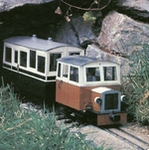
The 0-6-0 chassis are an awful lot of work due to the amount of cranks, con rods and hand made bolts / spacers it uses. The 0-4-0 chassis are a bit easier and are shown above with the little diesel bodies, the green one and the weathered one. I tried different shaped cranks on each one, just to see what they would look like and I am happy with the end result of both of them
The buck stops here .......
Ditton Meadow Light Railway (DMLR)
Member of Peterborough and District Association
http://peterborough.16mm.org.uk/
Ditton Meadow Light Railway (DMLR)
Member of Peterborough and District Association
http://peterborough.16mm.org.uk/
Re: A bit of time in the shed
Hi Steve
there would of course be no advantage in driving from the jack shaft it was just a thought. On one of the threads someone is asking for recommendations on a battery loco to use to rescue stranded steamers (pprobably with train). Would your locos be up to that sort of job, obviously with suitable batteries and weighting? I like the look of the 0-4-0.
Don
-
-steves-
- Administrator
- Posts: 2421
- Joined: Thu Jul 28, 2011 1:50 pm
- Location: Cambridge & Peterborough
Re: A bit of time in the shed
Indeed, I agree, there is no advantage from driving from the jack shaft, but it would have still been nice to if it were easily doneDonW wrote: ↑Tue Sep 03, 2019 5:14 pm Hi Steve
there would of course be no advantage in driving from the jack shaft it was just a thought. On one of the threads someone is asking for recommendations on a battery loco to use to rescue stranded steamers (pprobably with train). Would your locos be up to that sort of job, obviously with suitable batteries and weighting? I like the look of the 0-4-0.
Don
The chassis I make use exactly the same motors and gearboxes as Essel and GRS chassis. They are heavier than the GRS ones as I, like Essel, use brass for the ends of the chassis instead of just sheet steel. They are pretty heavy as the entire chassis is made from sheet steel and brass, with steel turned wheels, steel turned cranks, steel con rods, stainless steel axles, phosphor bronze bearings and plastic gears which ere easy and cheap to replace but last a very long time. I have not tried to use one as a recovery loco, but if a standard Essel based chassis loco or GRS based chassis loco works, then these should work just as well.
I must admit my recovery loco I built used 2 GRS based chassis (before I started making my own) and I added a heap of steel underneath it. From memory I think it came out over 12lbs! (5.6KG)
The buck stops here .......
Ditton Meadow Light Railway (DMLR)
Member of Peterborough and District Association
http://peterborough.16mm.org.uk/
Ditton Meadow Light Railway (DMLR)
Member of Peterborough and District Association
http://peterborough.16mm.org.uk/
Re: A bit of time in the shed
I'am first in line for one of them...... 
ROD
Life is so easy when I run my trains.
https://gardenrails.org/forum/viewtopic ... 41&t=11364
https://www.youtube.com/@fairywoodlightrailway
Life is so easy when I run my trains.
https://gardenrails.org/forum/viewtopic ... 41&t=11364
https://www.youtube.com/@fairywoodlightrailway
-
BorisSpencer

- Fireman

- Posts: 251
- Joined: Thu Apr 05, 2018 2:36 pm
- Location: East Northants
Re: A bit of time in the shed
12lbs, I'd have to strenghten my track beds, the Comfrey and Geranium only has a Light Railway licence!
More seriously, if your looking to shift some units, PM me a price and lead time. Having followed your build thread they will be more than capable for my needs.
-
tom_tom_go
- Driver
- Posts: 4824
- Joined: Wed Feb 23, 2011 3:08 am
- Location: Kent, UK
- Contact:
-
-steves-
- Administrator
- Posts: 2421
- Joined: Thu Jul 28, 2011 1:50 pm
- Location: Cambridge & Peterborough
Re: A bit of time in the shed
That can happen if you like and quite soon. Would you prefer an 0-4-0 or an 0-6-0 with Jack shaft to start with?
Steve
The buck stops here .......
Ditton Meadow Light Railway (DMLR)
Member of Peterborough and District Association
http://peterborough.16mm.org.uk/
Ditton Meadow Light Railway (DMLR)
Member of Peterborough and District Association
http://peterborough.16mm.org.uk/
Who is online
Users browsing this forum: No registered users and 3 guests