Cruise control for live steam + 433MHz Radio Control

What is your latest project?
Post Reply
User avatar
dewintondave
Trainee Driver
Trainee Driver
Posts: 697
Joined: Mon Mar 07, 2011 8:52 am
Location: New Zealand

Cruise control for live steam + 433MHz Radio Control

Post by dewintondave » Sun Jun 03, 2012 5:48 am

Here's the start of the build details for Dave's cruise-o-matic. 8)

A fellow G1MRA member inspired me to have a go at building cruise control for my live steamer. His controllers are based purely on electronics with no software. I don't have much electronics know how. Then I discovered the excellent Picaxe system http://www.picaxe.com/, and the rest is history...

The aforementioned G1MRA member also uses 433MHz radio control for his steamers. And I had a go at this as well.

433MHz is the garage door opener / wireless door bell type frequency. Keyfob size transmitters are freely available. I bought a Tx and Rx module from Ebay recently, here is the link:

http://www.ebay.com/itm/330734446785?ss ... 1439.l2649

Seller: http://myworld.ebay.com/xyfs-us/

These are really good value with free worldwide shipping and the seller is excellent.

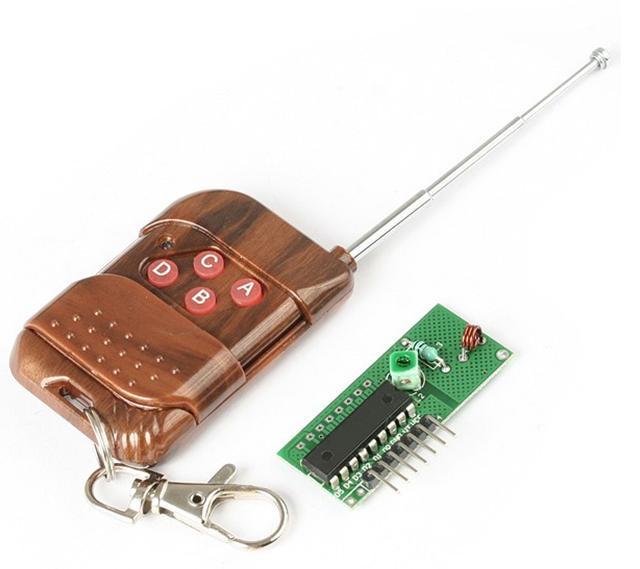
This is what the Tx and Rx look like, the transmitter even with classy woodgrain effect finish :)

Image

This system has 4 channels but I'm only using two at present. On my set-up, button D starts and stops the train and sounds the whistle at the same time. Pressing any other key will just sound the whistle.

The 433MHz system is very light on battery power compared to the usual model aircraft type controllers which are constantly transmitting instructions at a great rate, even when not appropriate. My 433MHz transmitter only transmits when a button is pressed, and the receiver only draws a few milliamps. As with the usual radio controllers current is being sent to the servos even when they are still, this is to maintain position. So I turn off the servos when they are not in use, like when the stop train button has been pressed and when the whistle is not being blown. The system is glitch-free and the range is adequate for my garden.

I have fitted the control system in a trailing truck, here is the rig:
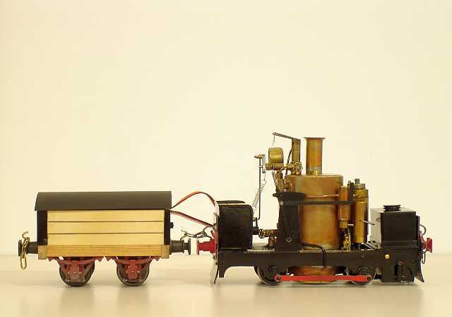
Image

There are two servos in the bunker; a mini servo on the bottom controlling the regulator and a micro servo glued on top of it, this pulls the whistle cord. I've used a spring in the whistle cord to give the whistle lever a full pull without straining anything.
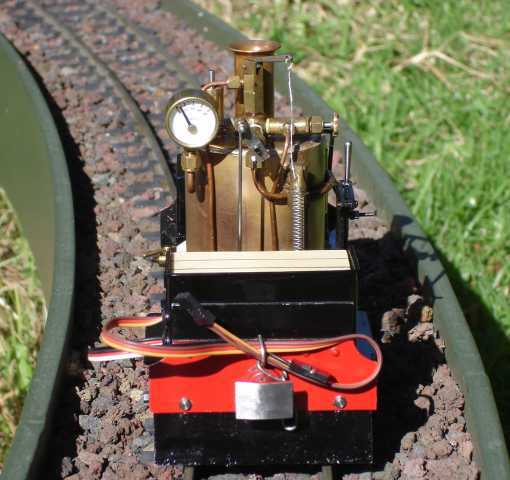
Image

Here is a video of the loco doing a circuit of our track, the first minute or so deals with the loco preparations:


To be continued...
Last edited by dewintondave on Thu Sep 03, 2020 2:25 am, edited 1 time in total.

User avatar
dewintondave
Trainee Driver
Trainee Driver
Posts: 697
Joined: Mon Mar 07, 2011 8:52 am
Location: New Zealand

Post by dewintondave » Tue Jun 05, 2012 1:12 am

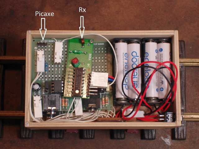
Here is the trailing truck contents; all the control gear.

Image

I'm using Picaxe M08M2 chips on three of their excellent AXE021 Proto Board Kits. These proto boards and chips are inexpensive. As per the Picaxe recommendations I'm using separate power supplies for the Picaxe's and for the servo power. These are 4 AAA cell eneloop rechargeables. The Picaxe cannot take 6 volts, so if non-rechargeables were used only a 3 cell battery pck should be used.

Theres a lot of spaghetti wiring. All the PCBs, the IR sensor, the RC Rx, and the batteries are need to be well grounded to each other.


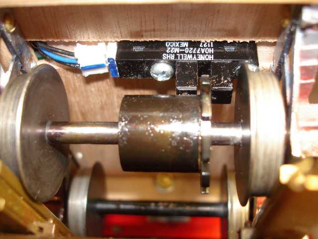
Here is the excellent Honeywell HOA7720-M22 IR sensor attached to the floor of the car.

Image

This sensor is really good as it has an in-built Schmitt trigger, this provides a nice fat high/low output. It only needs three connections, the two power lines and a signal out.


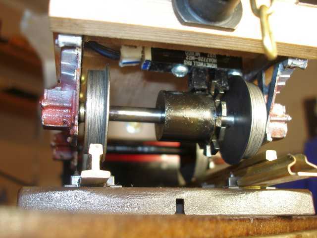
Here is a shot of the slotted-disc type counter wheel attached to the axle.

Image

I'm using a 10-slot counter wheel. This breaks the infra red beam from the sensor. The sensor converts this into the digital pulse. The picaxe counts the pulses over a time frame, and then outputs whether the count is high or low.

I'm using three Picaxe proto PCBs, the first counts the pulses, the second is the regulator servo controller, the third is the R/C receiver controller and whistle servo controller.

to be continued.

Dave.
Last edited by dewintondave on Thu Sep 03, 2020 2:28 am, edited 1 time in total.

11thHour
Trainee Fireman
Trainee Fireman
Posts: 117
Joined: Mon Mar 26, 2012 4:00 am
Location: Wodonga, Vic. Land of Oz

Post by 11thHour » Tue Jun 05, 2012 4:35 am

Waiting with bated breath ...
This could be the difference between a very small layout and an empire with some grades.
Tim

User avatar
dewintondave
Trainee Driver
Trainee Driver
Posts: 697
Joined: Mon Mar 07, 2011 8:52 am
Location: New Zealand

Post by dewintondave » Tue Jun 05, 2012 4:59 am

11thHour:71497 wrote:Waiting with bated breath ...
This could be the difference between a very small layout and an empire with some grades.
Tim
Hi Tim, check out my latest video with a heavier test train:


The little loco can really haul. The 180 degree bend at the end of the running loop is a very steep descent about 100mm, but very tight about 1 metre radius.

Dave.
Last edited by dewintondave on Thu Sep 03, 2020 2:30 am, edited 1 time in total.

User avatar
dewintondave
Trainee Driver
Trainee Driver
Posts: 697
Joined: Mon Mar 07, 2011 8:52 am
Location: New Zealand

Post by dewintondave » Wed Jun 06, 2012 6:35 am

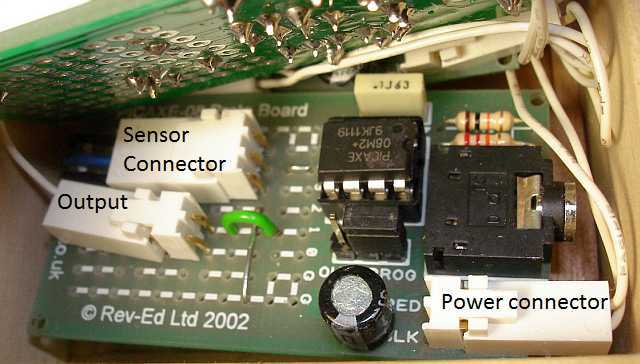
Here's the counter board.
Image


The power connector feeds in the 5V from the batteries. The sensor connector supplies +5V and Gnd from the board and receives the sensor signal from the central blue wire. The blue wire feeds through to port 4 on the Picaxe. The output from the Picaxe is on port 1. The output connects to the servo board.


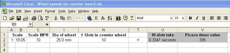
Here's a shot of my Excel spreadsheet to calculate the timing.
Image


The spreadsheet was used to calculate the Picaxe timer value for 10 slots of the counter wheel at a scale 10 mph.

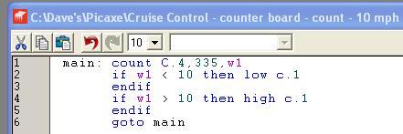
Here's a shot of the Picaxe programmer showing the simple instructions that I am using.
Image

The instruction states to count the pulses on port 4 for 0.335 seconds, and store the number as w1. Then if the number is less or more than 10 set the output port 1 high or low.

Picaxe starter kits AXE003/AXE003U contain the proto board, the chip, the programming cable, and all the software required.

To be continued.

Dave.
Last edited by dewintondave on Thu Sep 03, 2020 2:34 am, edited 1 time in total.

User avatar
dewintondave
Trainee Driver
Trainee Driver
Posts: 697
Joined: Mon Mar 07, 2011 8:52 am
Location: New Zealand

Post by dewintondave » Thu Jun 07, 2012 5:08 am

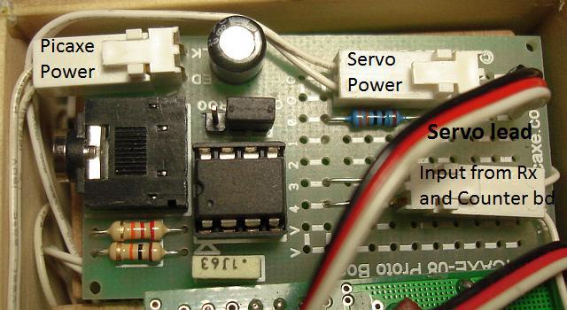
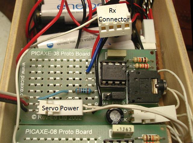
Here is the regulator servo board.

Image

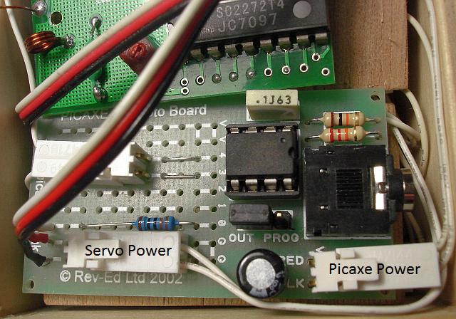
This board has a separate power supply for the servo, this was recommended to keep "noise" out of the Picaxe power supply. You can see the servo connect cable, it is now soldered direct to the board. The colour code of the cable is red for +5V, black for 0V - Gnd, white is the signal from the picaxe. There is a 330 Ohm resistor between the Picaxe output on port 0 and the white servo lead.

The Gnd for both power supplies are connected on the boards - the lower track on the image below is the 0V track. It is essential that all the boards, the Rx, and the IR sensor all share a comon ground.

The other white connector has the signal from the receiver - Rx connected direct to Picaxe input port 4, and the signal from the counter board connected to Picaxe input port 3.

Here is another view of the regulator servo board with the Rx above it.

Image


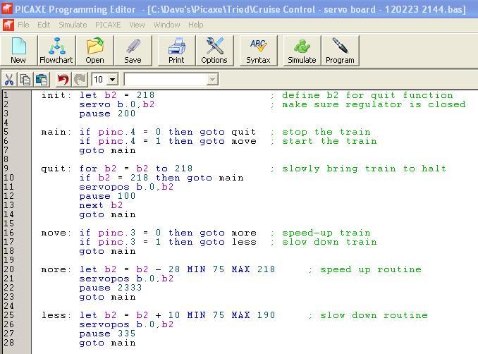
Here is a screenshot of a Picaxe program that I have used.

Image

This program at switch-on moves the regulator to the stop position if it isn't already. Then the program waits for the start button press on the transmitter. When the button is pressed the program shoots down to the more: section as the loco is stationary and applies the regulator, then waits for the loco to build-up speed, then returns to the main: section. In the main: section the program checks to see if the stop button has been pressed. Then the program proceeds to the move: section to check whether the loco is above or below speed. And so on.

I'm using a more complicated version now but this one explains the system easily.

Next I'll describe the regulator servo positions.

Dave.
Last edited by dewintondave on Thu Sep 03, 2020 2:36 am, edited 1 time in total.

User avatar
dewintondave
Trainee Driver
Trainee Driver
Posts: 697
Joined: Mon Mar 07, 2011 8:52 am
Location: New Zealand

Post by dewintondave » Fri Jun 08, 2012 5:08 am

Regulator servo positions.

The regulator servo needs to be mounted to the loco and hooked-up to the regulator just like on a radio control set-up. I'm using a Futaba mini servo on mine.

The next thing is to determine the required servo positions.

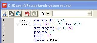
This little program can be loaded on to the Picaxe, it is using port 0 as the servo output. This program sets the servo swinging over its entire range of movement (position 75 to position 225). The program can be altered to hold the servo in any of the positions.

Image

My set-up now has regulator fully closed at pos. 225 and my largest regulator opening is set to 80.

The secret to my set-up is the pre-set minimum regulator position for when the loco is running. For me this is the required regulator setting for my loco to cruise along my straight level sections.

These are my current regulator settings for running, they feature in my video of Albus hauling the heavier test train:

225 - Fully shut off (quit: position)

201 - Minimum setting for running

161 - 1st application of regulator after starting sequence

147 - Starting regulator position / 2nd application of regulator

100 - 3rd application of regulator

80 - 4th application of regulator

To be continued.
Last edited by dewintondave on Thu Sep 03, 2020 2:38 am, edited 1 time in total.

User avatar
dewintondave
Trainee Driver
Trainee Driver
Posts: 697
Joined: Mon Mar 07, 2011 8:52 am
Location: New Zealand

Post by dewintondave » Sat Jun 09, 2012 4:09 am

It's time for the whistle servo board and the receiver.

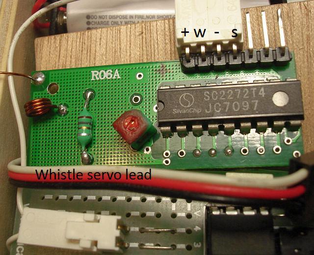
Here is the whistle servo board. The receiver connector is also visible.

Image

The whistle servo board provides power for the reciever, and takes the whistle signal from the Rx on input port 4.

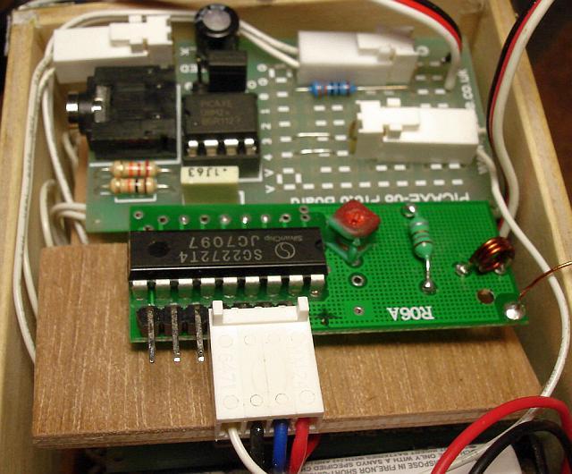
This image shows the Rx and the regulator servo board. The whistle board is under Rx.

Image

Here is the receiver with the connector in place. There are three channels that aren't being used

Image

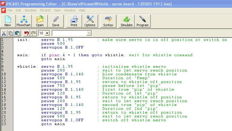
Here's the program for the current "peep-pip-pip" whistle sequence.

Image

This program switches off the whistle servo when not in use, and hopefully saves plenty of power.

There are pauses in the sequence to allow the servo to return to the whistle off position (position 95). Servos aren't too fast on 5V. I'm using a cheap micro servo for the whistle.

I think this installment wraps up the project.

Best wishes,

Dave.

Post Reply

Who is online

Users browsing this forum: No registered users and 13 guests